There’s an old saying that a picture is worth a thousand words. If you’ve ever tried to build furniture or a toy with one of those instructions sheets that contains nothing but pictures, you might disagree. 3D design is much the same for a lot of people. You think you want to draw things graphically, but once you start doing complex things and making changes, parametric modeling is the way to go. Some CAD tools let you do both, but many 3D printer users wind up using OpenSCAD which is fully parametric.
If you’ve used OpenSCAD you know that it is like a simple programming language, but with some significant differences from what you normally use. It is a good bet that most Hackaday readers can program in at least one language. So why learn something new? A real programming language is likely to have features you won’t find readily in OpenSCAD that, in theory, ought to help with reuse and managing complex designs.
I considered OpenJSCAD. It is more or less OpenSCAD for JavaScript. However, JavaScript is a bit of a scripting language itself. Sure, it has objects and some other features, but I’m more comfortable with C++. I thought about using the OpenCSG library that OpenSCAD uses, but that exposes a lot of detail.
Instead, I turned to a project that uses C++ code to generate OpenSCAD output, OOML (the Object Oriented Mechanics Language)). OpenSCAD does the rendering, exporting, and other functions. Unfortunately, the project seems to have stalled a few years back and the primary web-based documentation for it seems to be absent. However, it is very usable and if you know how to find it, there is plenty of documentation available.
Why not OpenSCAD?
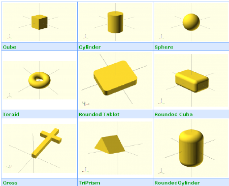 Obviously, there’s nothing in OOML that you can’t do in OpenSCAD. Which is like saying you can do everything C++ does in assembly language: it is true, but kind of misses the point. First, OOML defines many more basic objects (see below for a graphic taken from a white paper about OOML). If you want, for example, a RoundedTablet, you simply create one and the final output will have the necessary OpenSCAD.
Sure, you could define that stuff with a module. There’s also a library of parts including Arduino outlines, bearings, and other useful components. But the real value is that you can bring to bear all of the C++ features to developing new shapes.
Here’s a simple example. One of the parts available is the shape of a generic ultrasonic transducer module. The class provides a constructor that lets you set the different attributes like the size of the board, the size of the sensors, and more.
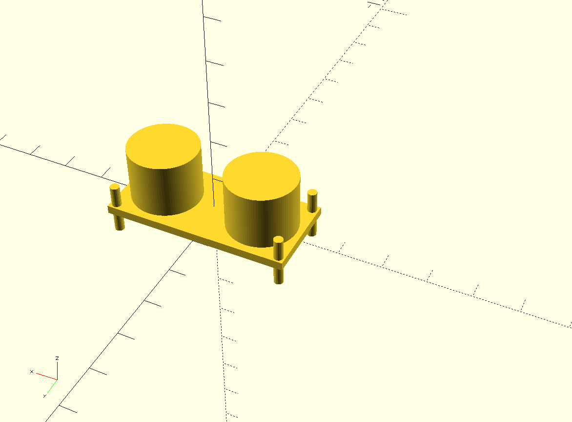 There is also a part that is a specific brand of ultrasonic sensor (one from Seeed Studios). Here’s how to create one of those in an OOML C++ program:
 SeeedUSSensor sensor;
That’s it. Here’s the definition of the SeeedUSSensor constructor:
 SeeedUSSensor(bool fill_drills = true) :
 USSensor(43,20,15,2,40,17,1,16.1/2,20-16.1/2,fill_drills)
 {
 rebuild();
 }
That’s out of context, but there’s nothing else significant in that object. All the rendering is in the USSensor base class. I could as easily make my own class for a Seeed sensor on a bracket, for example. I would just derive a new class and provide the additional rendering (or I could use any other C++ technique such as making my new object instantiate the sensor object).
Another feature that isn’t necessarily compelling is that I personally like the syntax. Here’s how you translate an object in OpenSCAD:
translate([10,10,0]) cube([5,5,10]);
Here’s the same code in OOML:
Component cube(Cube(5, 5, 10));
cube.translate(10,10,0);
If you want to take a union and a difference of some OOML objects:
result=cube1+cube2-boltholes;
Documentation is Like Oxygen
At one time there was a Wiki with documentation about the project, but it has either moved or is gone. However, the project is set up to do Doxygen documentation. It isn’t complete, but it is over 2,000 HTML files (which is probably why it isn’t on GitHub). You can generate it easily, but to save you the trouble, I forked the project and added the documentation as a ZIP file you can download.
The other way to learn about OOML is to read the source code. In particular, the test subdirectory has everything from a simple cube, to some fairly complex shapes. If you dive into the src directory you can also find examples of interesting things like the ultrasonic sensor I showed you earlier.
Usability
Having the power of C++ at your design fingertips is nice. What isn’t nice is losing the immediate design cycle you get with OpenSCAD. Being able to just tweak a number, hit F5, and repeat is pretty addicting. Using things like the octothorpe (I have too many British friends to call it a pound sign) to visualize a cut is a big loss, too.
You can’t do much about the special characters unless you read through the OpenSCAD code and find the right spot to put it (which somewhat defeats the purpose of using OOML). However, you can help get a little more immediate feedback with some setup.
All you need to do is open up the generated OpenSCAD file one time. Then make sure that “automatically reload” is checked on the Design menu. Now when you rerun your executable program and write over the OpenSCAD, the program will detect that, ask you to confirm and reload the file. Not quite as handy, but not bad.
If you are just making a simple keychain, this is probably more overhead than you want. But if you are doing a complex design with a lot of pieces that you reuse, with small differences, it can be just the thing.
Something Simple
Here is a pretty simple OOML program. I factored out the drawing code from the part that writes the output.
#include <core/IndentWriter.h>
#include <components/RoundedTablet.h>
#include <components/Cylinder.h>
#include <iostream>
#include <fstream>

void render(IndentWriter &writer)
{
Component obj(RoundedTablet(100,100,5,25,true,false,false,false));
Component cyl(Cylinder(25,10));
cyl.translate(22,22,-2);
writer << obj-cyl;
}


int main(int argc, char **argv)
{
IndentWriter writer;
render(writer);
std::cout << writer;
return 0;
}
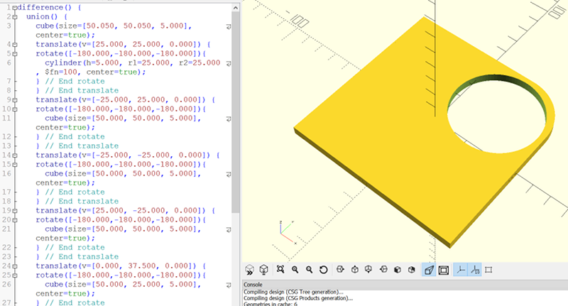
What that means is you can ignore the code in main and focus on the render function. I build a RoundedTablet with only one corner rounded (that’s not well documented, but you can figure it out from the parameter names). Then I cut a cylinder out of one corner. Granted, this wouldn’t be very hard to do in OpenSCAD and it doesn’t really show off the features you could use, but I wanted something simple to let you see how it works.
You can see the resultant OpenSCAD rendering at the start of this post. Once you have it at this point, you can do anything OpenSCAD can do.
Building
Since OOML doesn’t do any of the actual graphics generation itself, it is easy to build. I built a copy under Cygwin, but it should be about the same on Linux. You do need cmake installed. Here are the basic steps:
cmake .
make
make install
I did have to play with the DLL locations a bit on Windows, but that’s nothing new. To compile my example, I issued the following command:
g++ -o had -L ../lib -I ../src had.cpp -lOOMLCore -lOOMLComponents -lOOMLParts && ./had >had.scad
Note the part after the && actually runs the resulting program and then you still have to open the had.scad file (although just once if you turn on auto reload).
Give OOML a try. It is open source, so if there’s anything missing, you could add it to your own fork of the code. While I’d start small, the real power is when you want to build complex objects or systems of objects using C++. I can imagine a base class for chess pieces, for example. Or pulling data from a database to drive object creation.


I would like to see a tool that combined a C programming editor with a spreadsheet for doing calculations and visualizing results. I’ve used Excel to generate parametric code for smaller projects, but I’ll grant that it would be unwieldy for lengthy code.
There is a spreadsheet written in python that also uses python for scripting as well as various python front ends for the openscad engine. I don’t see the point of a compiled language for feeding data into openscad as all the heavy lifting is done by the engine anyway.
Nope, no python. I already know C and C++ a bit and examples here are looking sweet. I dislike python syntax either. It assumes dev is moron, and I thnik I would lose respect to myself if I would use lang like that.
And now I assume you are a moron, for dismissing python so quickly
The POV-Ray way of building things.
This is why I love OpenSCAD when I need to make a certain class of objects – that is, something more complex than I want to do in an ultra-basic app like Tinkercad, but something made with geometric precision out of addition and subtraction of basic shapes.
Spent a lot of time with POV-Ray in my youth (the closest to artistic I ever got) so it’s a very natural way to build such objects for me.
Ain’t nothing wrong with that!
The whole point of using a small, simple, domain-specific language like OpenSCAD, and not a general-purpose Turing-complete beast like C++ (with tentacles stamped onto a dog) is that you have fewer opportunities to make mistakes, easier debugging, fewer lines of code and you can easily guess what a piece of code does just by looking at it, because it will never do something that doesn’t make sense in this context. The whole idea is to have less power, so that you can hurt yourself less with it.
Yeah… but… if you are used to wielding C++ anyway, it isn’t bad to have a way to use the same tool to do the job. Sort of like a voltmeter vs an oscilloscope. I wouldn’t get a kid doing his first project nothing but a scope. But chances are if I’m doing anything serious, I will use the scope and not grab a meter even though it is simpler to use.
Of course, it is all OpenSCAD underneath, anyway, so don’t take my “ditching” comment too seriously.
Everything looks a bit like a nail…
Method calls seem an incredibly backwards way of expressing geometric transformations, given the reversed order of matrix multiplies.
On the other hand, learning a new language can give you new ideas to apply to the language(s) you already know and/or love. Sometimes you can even develop a new appreciation for something you thought you disliked. Picking up a new language is a great way to grow as a programmer
The other reason to use a language like OpenSCAD are the existant programs that are written and open sourced you can build off of.
I haven’t researched OOML, but my knee-jerk reaction is: why isn’t this article about industry-tested and open-source BRLCAD??? It has a C++, TCL, a rudimentary but usable (for review at least) GUI, and my late efforts have been to wrap the TCL script within a Python library.
I was exposed to BRLCAD working with the Army. I haven’t looked at it lately, but it was a pretty steep learning curve. It does do a great job, though.
Have you actually tried to use BRLCAD? Going to it from OpenSCAD is like going to Assembly from JavaScript. And if you’re coming from anything else, it’s like trying to be the Chinese Room with no instruction manual.
Blender is god-damned obvious and intuitive compared to the learning curve of BRL.
Yes, I have! I am actively using it for MEMS design, where I have nanometer scale features as well as millimeter scale features. The dynamic range BRLCAD supports is one of the key features why I have actively stayed away from other tools. To make the learning curve easier for myself, I’ve been writing a Python library to code all my parametric models… check out my github repo for examples… I’ve even implemented slicing (no 3D printer toolpath generation, only slicing and raster output, for my lithography masks)…. all in BRLCAD. http://github.com/nmz787/python-brlcad-tcl
Hey, I am one of the creators of OOML. It is great to see it here after some years. Unfortunately we could not keep on developing, but it would be great if someone would take it on. I would certainly contribute.
Among the goals it was not only designing in c++, but being able to use powerful c++ libraries into complex designs, or using matrix libraries to compute parameters…
It would be great to see this work continued, although maybe now I would choose python.
@avalero Have you ever used the Sverchok plugin for Blender3D? It is a parametric modeler, but it uses Blender’s node ui elements to represent its flow. Under the hood it is probably all python, as Blender3D’s api is python.
You mean https://github.com/SolidCode/SolidPython
SolidPy on github is the same idea in Python. It worked a few years back when I used OPENSCAD.
I have been coding C++ professionally for 20 years, but I use SolidPython with OpenSCAD. It works very well indeed.
Thanks! I wrote a python script myself which does basically the same thing (only much more personally tailored of course). I will definitely take a look into SolidPy!
Documentation is like oxygen but Doxygen is not like documentation. -_-
Openjscad has recently landed some code that makes it suitable for running under node.js, so it ends up in a similar situation.
Why not – https://github.com/SolidCode/SolidPython
OpenSCAD with the benefits of Python
Because the core of openSCAD (openCasCade) crashes and doesn’t have good unit tests.
nope. it doesn’t – some made a request to integrate openCASCADE in 2011 but no.
It does use CGAL – which does the minkowski and some other boolean tricks. Over time slowly it is being superceded.
Sorry I misattributed the crashes and instability…
Plugging: http://www.implicitcad.org/
Same thing based on Haskell. Was featured on HaD before iirc.
Doesn’t yet work for complex models with large dynamic range… I know because a model I wrote for implicitcad is being used by the developers as a test case.
True… Actually I don’t think it is under active development anymore. Which is sad, because Haskell is a great language to embed domain specific languages in.
Being a “mostly software” person, my personal trajectory concerning CAD might be interesting to other people.
Here are the stages I went through:
– Stage 1: Couldn’t do anything because every time I tried a CAD program it either crashed under my fingers (FreeCAD) or my head exploded (Rhino, Fusion, a few others). I am also a post-mouse and one-button person, which complicates matters.
– Stage 2: Discovered OpenSCAD and used it happily until I wanted to do things with fillets. Now I could design things, but they always look like things from OpenSCAD. (Yeah, there is a lib for fillets if you can wait a few hours, or days in my case, to render things and mess up you source code beyond recognition…)
– Stage 3: Learned how mechanical engineers do actually communicate designs to the colleagues in the machine shop. For this I took a few lessons using pencil and paper, literally, from a mechanical engineer by training. (She also happens to be my wife.) A hallmark of mechanical design is properly understanding and communicating tolerances.
– Stage 4: Bought a license of QCAD, a serious and well designed 2D CAD program. Greatly improved on the pencil and paper method by the second bugfix at the lastest. (I understand how someone can design the HMS Titanic in 2D, but how did they do that on paper?) Could produce reasonable 2D drawings the machine shop can work with.
– Stage 5: Discovered Onshape.com, a professional constraint-solving 3D CAD program running on Onshape’s servers and your browser. Freemium marketing model. Followed a few tutorials and designed some things. Now I could create genuine 3D designs of parts and assemblies and derive 2D drawing from these, which is another creative process and not a mathematical operation as I had assumed before stage 3.
– Stage 6: Wrote some programs in Onshape’s extension language (“FeatureScript”). This enableed me to define complex parametric geometry by code, and the functions can be made to show up in the GUI like any other operation. This took me full circle to designing 3D artifacts by typing source code, but I don’t need to do that as often as I used to because 3D CAD has lost its menace… (And a huge thanks to N. for that!)
– Stage 7: Become horribly disappointed when Onshape.com changes their model / is hacked / goes down / goes out of business / decides they don’t like you / changes their rates / has a bug / cannot connect to you because your internet is down / a whole host of other possible issues.
– Stage 8: Write your own CAD program.
– Stage 9: Support groups and companies who do not force you to use them as a cloud only provider.
I don’t see where they’re forcing you to use their product. If you wanna use SolidWorks instead, more power to you – just make sure you’ve spent all that extra money on hardware to run it.
Cloud based services have their advantages as well as downsides; if you’re ignoring products only because they’re “in the cloud” then you’re missing out on options that may actually be perfectly suited to your use cases.
Yes, AngelCAD https://arnholm.github.io/angelcad-docs/
Generic “/”-ing aside, Onshape was, and is, a very valuable learning resource to me. It allowed me to step from the world of OpenSCAD into the world of professional 3D CAD for mechanical engineering. Of course this does not make me an expert in mechanical design but I got an idea “what exactly it is that they do,” and I did some things myself. Buying a (non-student) license of SolidWorks, Creo or Solid Edge for this limited goal was exceeding the budget, and Fusion 360 didn’t cut it for me at all.
So.. you never tried Inventor or Solidworks?
It’s kinda disappointing that it just uses OpenSCAD and the rest of the usual tools on the backend. It’d be much more interesting to see something that operates on Signed Distance Functions, and generated the gcode directly from that, avoiding triangular tessellation. The other advantage is that stuff like filleting which is difficult in OpenSCAD would become trivial.
I noticed that up to this point neither the article nor anyone else mentioned gcode, 3d printers, cnc machines or anything else gcode related.
Do OpenSCAD models ever get used for anything else? Maybe electronic artwork, videogame pieces, etc… If so then maybe that’s your answer. You can always get to g-code through OpenSCAD anyway.
The principle output format of OpenSCAD is STL, which is pretty much a bunch of triangles, and is pretty specifically a 3D printing oriented format.
My point is, though, that when you’re specifying your model in terms of composite curved geometry, and realising it as stacks of curved blobs of plastic, it seems somewhat counterintuitive to get between the two through the use of triangles. It also introduces ugly faceting, which in turn leads to the punishing slowness of openSCAD when you crank up the facet-per-arc parameter to nice levels.
I actually do use OpenSCAD sometimes to do 2D projections output for DXF that I used for nefarious purposes unrelated to 3D printing.
SolidPython is my favorite ;)
https://youtu.be/G3_wUxaHBM8
I would prefer .NET/C#
I even made few experimental models with it
https://www.youtube.com/watch?v=dlQ3HhHRtSU
Ok, I think you misunderstood the concept of ‘Parametric CAD’. That video looks like an old-style OpenGL vertex and face rendering pipeline. Even stuff like defining a cube by width, height, depth is not really parametric CAD on its own. The word parametric in Parametric CAD is in the “parametric equations” sense. The power of parametric CAD comes in part from things like dimensions, which are constraints that help the CAD system solve parametric equations to determine where all the vertices are. If you don’t have a parametric equation solver and probably an arbitrary precision math platform, you’re not a real parametric CAD platform, just some other simpler CAD or rendering engine.
on video is just an minimal workable demo.
And I know what parametric cad is, and this is fully functional c# code so it can use power of .NET like Math or load JSON and put result as a dimention
Ohh, they are worth 1000 words, but they don’t specify which 1000. In there lies your problem, each person will pick a different 1000 words to describe that picture, most of which will overlap but the differences may be significant and crucial in the case of visual instructions.
Well, a picture is worth 1000 words. 1200 Canadian.
If Canadian was implemented in Python then you could get it down to100 words.
How timely — I’ve been working on a project that uses Eclipse’s XText framework to build a full-featured IDE for OpenScad. XText uses antlr under the hood, so the guts of the project use a parser for OpenScad language. There is such a thing already (eSCAD by Patrick Lie — http://www.patricklie.com/projects/escad/), but it’s rather like a skeleton of a real XText project.
Such a tool could be used very similarly to OOML, but in Java, because with a parser now you can import arbitrary openSCAD code, and in theory then you can refactor it, or generate your own.
Is anyone interested in this? It’s not clear whether I’ll continue to develop it, but if there’s interest I’d consider open sourcing it.
Something like OpenSCAD for _complex_ designs? A person saying this apparently never did really complex shapes. As soon as freeform surfaces enter the picture: good luck! Modifying a casting part with hundreds of ribs and everything filleted: also good luck!
Modifying a part with hundreds of ribs/fillets would be a simple task, assuming you’ve written simple and extensible code.
Freeform surfaces would be a harder trick… unless you can redefine those freeform surfaces as explicit functions, then you’d be good. Again, better programming is key.
Problem here. Right now there is no, and I mean fucking NO, opensource software that is even at the startingline when it comes to compete with any professional CAD, be it Inventor, CATIA or SolidWork, unfortunately. Maybe one reason why they cost that much is, it uses that much manpower to develop.
Inventor is as well as most AutoDesk tools this day, free to use for noncommercial stuff. Noncommercial is less then 100000$ income with this tool per year, afaik.
Dassault provides one SolidWork license per Fablab. So make your own Fablab ;).
BTW: as they are a weapon manufacturer as well i see no ethical problem “stealing” software as well, but that’s my two cents and I don’t recommend you to do so ;).
I’ve heard this complaint before, but I haven’t seen a list of features/functions that a package needs to be professional-ready. What specific missing features are critical for you?
Can’t wait to download someone else’s designs and have to execute arbitrary c++ on my computer!
Hackaday kudos to the first 3D-model virus.
i will stick with autodesk inventor, ease of use and capabilities are so much better :/
There’s also openjscad, blockscad, onshape’s feature scripts, and all the Python in the world with FreeCAD.
irit http://www.cs.technion.ac.il/~irit/
been around forever and is incredibly rich and powerful. also now has a python interpreter.
Hi Al
I am trying to get your ooml example running in Eclipse on Linux Mint, but I get the following error message, which I can’t interpret.
Can you or someone of your followers eventually give me a tip, what’s wrong and what to do about it.
I am stuck since a couple of days.
Thanks in advance Bo
10:39:44 **** Incremental Build of configuration Debug for project AOOMLPathFinder_030918_1005 ****
make all
Building file: ../src/components/Cube.cpp
Invoking: GCC C++ Compiler
g++ -O0 -g3 -Wall -c -fmessage-length=0 -std=c++17 -MMD -MP -MF”src/components/Cube.d” -MT”src/components/Cube.d” -o “src/components/Cube.o” “../src/components/Cube.cpp”
In file included from ../src/components/Cube.cpp:9:0:
/home/bo/ooml2.0/ooml2.0/src/components/Cube.h:44:33: fatal error: core/AbstractObject.h: No such file or directory
compilation terminated.
src/components/subdir.mk:18: recipe for target ‘src/components/Cube.o’ failed
make: *** [src/components/Cube.o] Error 1
10:39:44 Build Finished (took 72ms)
I already learned openjscad because openscad’s programming language is terrible. Unfortunately I had to abandon openjscad due to rounding errors in the intersection function that they won’t fix.
I’d be interested in more examples of ooml. Unfortunately I don’t see much activity on the project, and the github page has disabled the issue tracker. So I don’t know if other people are having problems with it.
I made some examples of how to generate stl files using C++ and vtk. The one problem I’ve had so far is that vtkbool will only do a union if the objects intersect.
https://github.com/bluelightning32/vtk_print_examples
Hi
Can I perform CSG operations with this library?
If you’re reading Al I’d love an update on what you use today