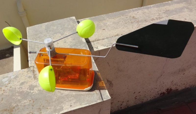
Problem: build a combined anemometer and wind vane where the pivots for both sensors are coaxial. Solution: turn an old universal motor into a step-wise potentiometer for the wind vane, and then pull a few tricks to get the whole thing assembled.
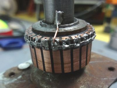
 We have to admit that when we first saw [Ajoy Raman]’s Instructables post, we figured that he used a universal motor to generate a voltage from the anemometer. But [Ajoy]’s solution to the coaxial shafts problem is far more interesting than that. A discarded universal motor donated its rotor and bearings. The windings were stripped off the assembly leaving nothing but the commutator. 1kΩ SMD resistors were soldered across adjacent commutator sections to form a series resistance of 22kΩ with taps every 1k, allowing 0 to 2.2V to be read to the ADC of a microcontroller depending on the angle of the vane.
As clever as that is, [Ajoy] still had to pull off the coaxial part, which he did by drilling out the old motor shaft from one end to the other using just a drill press. The anemometer shaft passes through the hole in the shaft and turns a small DC motor to sense wind speed.
There might have been other ways to accomplish this, but given the constraints and the low cost of this solution, our hats are off to [Ajoy]. We’re a little concerned with that motor used for the anemometer, though. It could result in drag when used as a generator. Maybe a better solution would be a Hall-effect sensor to count rotations of a hard drive rotor.


Quote: “We’re a little concerned with that motor used for the anemometer, though. It could result in drag when used as a generator”
This should be a non-issue. The returning cup of the three cups creates drag by wind resistance anyway. Your only measuring a ‘difference’ anyway.
brilliant & resourceful, well done
Interesting how he soldered the SMD:
“Soldering 1 kilo Ohm SMD resistors in 0805 package was quite tricky as the copper commutator segments quickly conducted the heat away from the soldering iron tip without allowing it to melt the solder.
I overcame this by placing a higher-wattage soldering on the main shaft to preheat the whole mass and then soldered the 1 kilo Ohm resistors between segments with a second lower-wattage soldering iron.”
Yep, there it is … degrees per watt. Just like any other heat sink.
Not quite sure how I’d have done it either. Possibly preheat the commutator with a blowtorch and tin the segments, then come back once it’s cooled a little to tack on the SMDs?
I kinda want to try this despite having a bin full of pots
A little bit of dust and a pot is next to useless. The commutator idea will still working after the apocalypse.
it’s simple, robust, and resourceful. I like.
great idea, kudos on the idea.
i would sugest getting it a little higher for more accurate readings. i think the buildings are making a lot of cross winds.
You have to work with what you have on hand, but the hard part is always going to be calibrating it accurately.