In the days before semiconductor diodes, transistors, or even vacuum tubes, mechanical means were used for doing many of the same things. But there’s still plenty of fun to be had in using those mechanical means today, as [Manuel] did recently with his relay computer. This post is a walk through some circuits that used those mechanical solutions before the invention of the more electronic and less mechanical means came along.
Coherer Morse Code Receiver
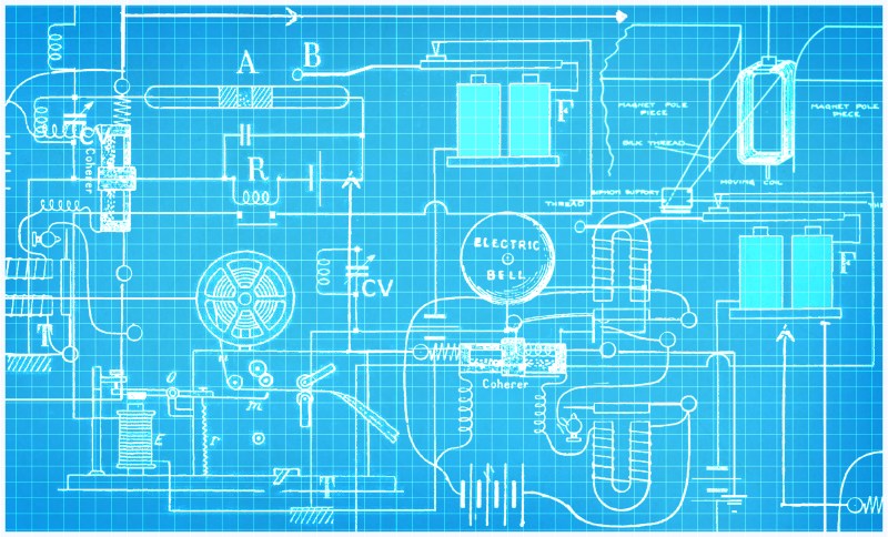
The circuit shown below is a fun one, especially if you’ve played with crystal radios. It receives Morse code that’s transmitted as bursts of radio waves at a specific frequency. The transmission back then was done using a spark gap transmitter. A dot is a short period of transmission at that frequency and a dash is a longer period of transmission. In between the dots and dashes, nothing is transmitted. This circuit decodes those dots and dashes and records them as indents tapped onto a paper tape. A dot results in one, or only a few indents, and a dash results in more indents. The tape is moved at a constant rate, and so the dots and dashes are spaced out by lengths of tape with no indents.
Across the top is the antenna. The wire descending from the antenna goes to the parallel LC resonant circuit consisting of a coil and a variable capacitor, CV. Together they tune in to the desired frequency. To the right and in parallel with that are coherer A and relay R.
The coherer is a tube consisting of two electrodes with metal filings between them. By applying the radio frequency across the electrodes, the filings cling together, actually forming tiny micro-welds between the granules, which makes the coherer conduct. In this way it functions as a radio frequency detector.

Prior to the coherer becoming conductive, the circuit path that includes the coherer and the relay is either open-circuit or the coherer’s resistance is too high to allow the relay to become energized by the battery that’s to the right of it. But once the coherer becomes conductive, the relay becomes energized and closes its switch.
That switch activates the circuit that consists of the two solenoids F, the solenoid E and a battery along the wire between E and F. That causes solenoid E to become energized and to attract the slug of metal on the arm that pivots at O, pushing the right side of the arm upward and tapping an indent into the tape.
Once the mark is made, solenoid E is remains energized, somehow it has to become de-energized. That won’t happen as long as the coherer is conductive, and that’s where solenoids F play a part.
When relay R closes its switch, energizing solenoid E, it also energizes solenoids F. Solenoids F attract arm B (the “tapper”) downward. That results in two things happening. Part of the circuit goes through a point halfway along arm B, and when it moves downward, contact is broken at that point. The circuit is opened, de-energizing all solenoids, and releasing the marker arm, which is pulled back down by spring r.
The other thing that happens when arm B is attracted downward is that the ball on the leftmost end of arm B taps on the coherer, breaking up the iron filings and returning the coherer to a low or non-conductive state. That also causes relay R to open its switch. So even though arm B relaxes back upward when solenoids F are de-energized, closing the circuit there again, the fact that relay R at the same time opens its switch means the circuit remains open. Needless to say, getting the timing of the two lever arms and the relay just right to make a small dot requires some adjustment.
But we’re not done yet. If a dash is being transmitted then the radio frequency is still being received and the coherer immediately becomes conductive again and the whole process repeats for another tap on the tape. Looking at old tapes, it seems that a dot also causes multiple taps, just not as many as a dash. Any Morse hand knows that a dash is three times longer than a dot. Now you know why.
[Ashish Derhgawen] made both a spark gap transmitter and a receiving circuit much like the above one, complete with a coherer tapping mechanism. But instead of writing the message on a tape, he sends it to a BeagleBone board for interpreting and displaying as English text on a monitor: a fully acceptable modern compromise.
Using A Bell Instead


This next electromechanical circuit is a variation of the previous one and was used by Alexander Stepanovich Popov for detecting approaching lightning storms.
Lightning emits electromagnetic waves of various frequencies. Some of those frequencies, when picked up by the antenna A, cause the filings in the coherer C to cling, making the coherer conductive. That closes the circuit C-L-V-R-L. Doing so energizes the relay R which attracts the arm just above it, closing the contact attached to that arm. That energizes the circuit that includes relay E. And doing that pulls up on the arm that taps the ball against the bell, ringing it.
But when the bell ringing arm is pulled up, it disconnects the arm from contact with that circuit, turning the circuit off. The bell ringing arm falls back down and has enough looseness for the ball to tap the coherer, turning off the C-L-V-R-L circuit too. So in this case the bell ringing ball serves double-duty as a tapper arm.
Why, you might ask, are the two chokes L needed? They’re present because there’s radio frequency noise from the relay contacts. That noise would make the filings in the coherer become conductive. The chokes prevent that noise from getting back to the coherer.
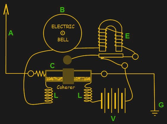
And a bigger question you might ask is why use two relays? Why not have just one as in this modified version? It looks like it would work. The reason Popov added the second relay was that the coherer couldn’t provide enough current to ring the bell itself. So the additional relay allows a circuit that’s independent of the coherer — a sort of mechanical amplifier.
Notice that the diagram shows the use of U-shaped electromagnets for the relays. Presumably that’s to take advantage of both ends of the magnetic field induced in the core. Once I thought about this I realized it was probably why the Morse code receiving circuit above uses two solenoids at F, something I was scratching my head over. The base that they sit on is likely iron, and counts as part of the core, and the way the solenoids are wound likely results in a north pole facing upward for one and a south for the other. The two solenoids and the base likely form the equivalent of a U-shaped electromagnet.
Adding A Siphon Chart Recorder


The photo shown here is one of Popov’s machines for ringing a bell when there’s a lightning strike, but it also records the strikes on a chart recorder. We don’t have a circuit for his specific chart recorder but that lead us to look deeper and find a diagram for an old, obsolete electromechanical siphon recorder that looked interesting enough to talk about.
The driving mechanism is a moving coil, like the ones found in analog meters. The coil is suspended between the poles of two magnets. As current moves through the coil it creates a magnetic field that reacts with that from the magnets, causing the coil to rotate a little in the vertical axis. The amount of rotation is proportional to the amount of current.
The coil is attached via threads to a rectangular object that’s mounted such that it’s also free to rotate a little in the vertical axis. As the coil rotates, those threads cause the rectangle to rotate too. A tube is attached to that rectangle, one end of which is in an inkwell, and the other end of which is lower down and faces a moving strip of tape. As ink is deposited on the tape, more ink is siphoned from the inkwell.
Endstop
And so that’s a fun romp through some old electromechanical circuits. We’d love to hear some of your favorite electromechanisms, or electroanachronisms, and especially any that you’ve either replicated or come up with yourself.


Ha, looking at my left, there is a mechanical serial to parallel and vv converter in the way of a ASR33 teletypwriter and looking to my right sits a Flexowriter programmatic with a big bunch of relays to change the behaviour of the machine.
To my left is a window and to my right there is a wall.
And a meme is born.
To the left: my man. Ahead: the man my man could smell like.
To my left is a Bed, good night!
Electro-mechanical pinball machines are a thing of beauty–no resistors, no capacitors, no transistors/diodes…Only coils and switches (and lots of relays, which are, of course, just coils and switches). Stare at the schematics for a few minutes and you’ll come to realize how the game works (ball hits switch, which energizes a scoring circuit, which triggers a change in the score reel/rings the bell/etc and which switches back to energizing the “main” circuit.) You can find schematics on ipdb.org, such as for the machine I own:
http://www.ipdb.org/machine.cgi?id=935
Are there really not even resistors to reduce contact wear (arcing)? I know a two coil setup for the flipper arms, where a quite strong coil pulls it in and a weaker coils holds it. It was an electronic flipper, but the strong coil was switched off by a leaf contact, as soon as the arm reached it’s end position. One of this was arcing very strong and on closer look it’s parallel RC combination had a broken solder joint.
The coherer is, in a way, the ancestor of the modern memristor.
In what way? The “fourth” electrical component (memristor) was unknown when the coherer was created. If memory (heh) serves, memristors relate electrical charge and magnetic flux, but coherers are more like phase-change memories, in that there are physical changes that occur from the RF current flowing through them, resulting in a lower DC resistance.
You both make good points, but Dan is right – it’s a very distant relative.
Hmm, vague memory of a tin can 3 inch long 1.5 diameter that was an oscillator maybe in car valve radios and other valve stuff. Can’t even remember what it was called now, inverter maybe. I do remember they used to fail a lot.
Vibrator, it produced a “square wave” from 6 Volts Direct Current. The square wave was fed into a step up transformer which provided plate voltage for the tubes(valves). I think a rectifier tube (valve) made the HV into DC again.
I replaced one in a bullet nose Studebaker about 20 years ago…
Here is a link to a schematic, the vibrator is in the lower right corner, by feeding a center tapped transformer it was making a 12 volt square wave.
The 0Z4 rectifier tube used ionized gas to rectify the transformer output.
As indicated by the 0 in the tube/valve name, it did not have a heater filament.
Doh!
http://www.rfcafe.com/references/radio-news/images/1957-auto-radio-chevrolet-schematic-apr-1957-radio-tv-news-3.jpg
As you can see on the schematic, a vibrator was also used when automobiles converted to 12 volt batteries.
Because for a standard tube either battery voltage is way to low as plate voltage.
there are some very low voltage tubes out there called space charge tubes or something,
those would have a extra grid to create a forward bias that would extend the electron field around the cathode.
http://www.junkbox.com/electronics/lowvoltagetubes.shtml
Well as far as that goes there were nuvistors, a type of vacuum tube made by RCA starting in 1959 that were low-voltage, low power and small. There were also so-called acorn tubes around earlier that didn’t need a huge B+ either.
DV82XL,
IIRC, Acorn tubes were for high frequencies, they had the leads for the internal elements exiting directly out of the side of the tube/valve to shorten their length and space the leads further apart from each other.
Here’s the wiki…
https://en.wikipedia.org/wiki/Acorn_tube
So were nuvistors, but nothing would have stopped you from using them at lower frequencies, the point here being that they were low voltage devices.
https://hackaday.com/2016/07/04/retrotechtacular-dc-to-dc-conversion-by-vibrator/
Thanks Al!
don;t forget Pinball machines – event based cam driven decision trees with decade counters
The Simon relay computer trainer built with with relays and a rotary dial from a desk phone, meant to help train students in schools which could not afford an actual computer.