Whenever I end up with a new vehicle I ultimately end up sticking in a new GPS/Receiver combination for better sound quality and a better GPS.
I am quite at home tearing into a dashboard as I was licensed to install CB radios in my teens as well as being the local go-to guy for 8-track stereo upgrades in the 70’s. I have spent a portion of my life laying upside down in a puddle on the car floor peering up into the mess of wires and brackets trying to keep things from dropping on my face. If you remember my post on my Datsun 280ZXT, I laid in that same position while welding in a clutch pedal bracket while getting very little welding slag on my face. I did make a note that the next time I convert a car from an automatic to a manual to do so while things are still disassembled.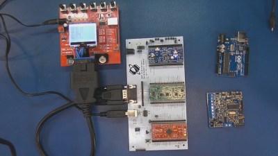
Swapping out a factory radio usually involves choosing whether to hack into the existing factory wiring wire-by-wire, or my preference, getting a cable harness that mates with the factory plug and making an adapter out of it by splicing it to the connector that comes with the new radio.
Usually I still have to hunt down a few signals such as reverse indicator, parking brake indicator, vehicle speed sensor and the like. In my last vehicle the Vehicle Speed Sensor (VSS) wire was supposed to be in the factory harness, but driving experience showed it must not be as the GPS would show me driving 30 feet to the right of the highway. That and the calibration screen on the GPS verified that it was not receiving speed pulses.
Finding the VSS Wire
Diving deep into the dash verified that a single wire was in fact missing in spite of being shown in the standard Haynes manual. Many times the VSS signal is on the harness for use by a GPS or for the automatic volume adjustment on the radio — as the vehicle goes faster the factory radio gets louder.
I checked all of my online installer resources and no one had identified the signal as present anywhere in the driver compartment. Finally I leased the Ford schematics directly from Ford and was able to identify a safe speed signal to use. I should note that I stay away from the wheel speed sensors for the anti-lock brake system, I am already freaked out by the thought that a microcontroller is running the brakes on my behalf. As it turns out there was a solitary signal that lets the windshield wiper controller speed up when the vehicle speeds up, like an automatic volume control only for wipers.
All of this effort got me thinking about how else I could have done this without running wires through the firewall and tapping one of 300 wires attached to the on-board Electronic Control Unit (ECU). In other words, how would a normal person do it?
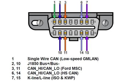
One thought I had was to put together a dedicated circuit that could query what the vehicle speed was from the built-in On Board Diagnostic bus (OBD or OBDII) and synthesizing a speed pulse from the resulting data. Looking on the Internet briefly I found that there was one company that did this for retrofitting taxicabs for the metering hardware but not much more than that. Besides all of that, I needed a topic for a Hackaday video.
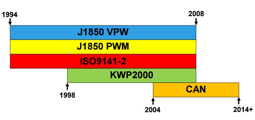
Here we see the years that the various OBD protocols were used and a quick summary.
|
Name |
Speed |
Used by |
|
ISO 9141 |
10 Kbits/second |
most Asian and European manufacturers |
|
J1850 PWM (Pulse Width Modulation) |
100 Kbits/second |
Ford, Mazda |
|
J1850 VPW (Variable Pulse Width) |
100 Kbits/second |
Primarily GM |
|
CAN (Controller Area Network) |
200-500 Kbits/second |
Newer Vehicles |
Looking into the OBDII connector and protocol the first thing that jumps out is that it’s not a single protocol; it is a collection of legacy protocols. Vehicles made since 2008 typically use the Controller Area Network (CAN) protocol.
One thing I knew was that I didn’t want to learn the intricacies of these lower level protocols and how to program at a bit or frame level, I just wanted to ask and get an answer to a simple question: “What is the vehicle speed?” In the video I do go into the different electrical interfaces for J1850, ISO9141 and CAN.
Reading CAN Data
I came upon an OBD interpreter chip made by OBD Solutions. It’s called the STN1110 and converts the physical and low level protocols into a simple ASCII based UART interface.
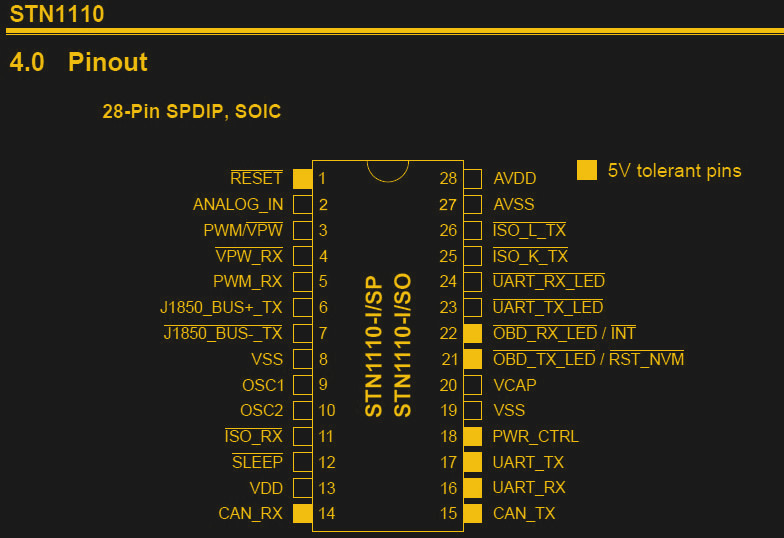
Sending a query for the Parameter Identification (PID) for Vehicle speed “010d” results in a three byte response with the third byte being the vehicle speed in kilometers and hour as a single byte hex value. (0-255 km/hr). From this data it’s just a matter of creating a pulse that gets faster based on the size of the VSS value, the larger the value, the higher the output frequency. I actually don’t know what the GPS expects as a normal frequency but being software, I can always scale it if I run into problems.
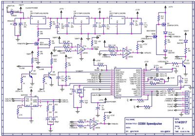 Looking at the datasheet for the STN1110 they give examples of the interface circuitry for the various protocols: CAN, J1850, ISO9141. If I were doing this project for production I would scrutinize the interfaces in great detail, but for a video and a one-off circuit I am more than willing to take the vendor’s suggested circuits as they most likely know the “normal” for what works.
What the designer still has to do is make sure that surge protection and that the current draw and the ability to “sleep” are designed in. With regard to surge suppression, the automobile is one dirty environment; huge inductors (starter, alternator) and lots of places where spikes and surges can be injected. With regard to current draw, the assembly would be plugged in “permanently” which means that it’s current draw must be minuscule while sitting for weeks on battery power. I once installed an alarm system in one of my cars which killed the battery in a week, it sucked.
Cramming Too Much On One Board Footprint
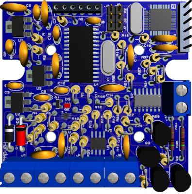
Looking at the board you will see I did an insane thing, I mixed surface mount and through-hole and not just any through-hole, I mounted the resistors radially, meaning that they stand up like the old Japanese radios of the 70s-80s. Part of the idea was what if I wanted to make a kit and the other is that I really hate placing 50 SMT resistors as they get in my arm hair and it’s easy to misplace them. The size of the PCB was selected to fit a plastic enclosure I picked off of Digikey.
Turns out once I got into everything I realize that if I pare the design down to just the CAN protocol (2008+) it will do everything I need and so rev 2 will be all through-hole so I can throw the spares up on Tinde as a kit.
Things work well enough with the final board with the exception of the fact that I missed that one of the LED indicator pins is also used to initiate a Non-Volatile RAM initialization… I mean who doubles an LED pin as an input pin? Even with the LED in place a resistor would be needed to tie it to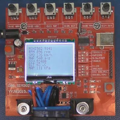 a known state since an LED that is turned off doesn’t conduct current or act like a resistor.
Finally at the end of the video I break out my cheapo OBD simulator which basically parks my truck on the work bench, electronically speaking. There are really good versions of these, mine is a $70 one I got off eBay. The instructions are in Mandarin but they really aren’t needed. Using a dev board with built-in USB connector simulates my custom board without the FTDI interaction I was getting between the Hackaday Pro Trinket and serial monitor. I set the baud for 9600 and issue the PID query for VSS: 010D (or $010D as I would say being an old timer)
It replies with B5 meaning that the simulator is traveling at 181 km/hr. (Decimal of Hex B5 is 181)
In the next post I address the software. Being a simple form of instrumentation my inclination is to implement this as a (simple) Real Time Operating System (RTOS) meaning that hardware counters and timers tied to crystal create the final signal that does not vary based on the execution time of the code. I am also inclined to use assembler (did you submit to the Hackaday 1k Challenge??) and because I am a hardware engineer I love true In circuit Emulators(ICE). You know, where you actually see the execution of the processor itself and can set true breakpoints (An IDE is not an ICE). See you next time!







Nice job, seems a bit disappointing that you had to lease the Ford schematics directly from Ford in order to more easily accomplish this though.
Yeah I had to come clean on the sin but the real effort was picking through all of them to find a signal used for stupid wiper blades. At least the GPS liked it.
Why not provide links at the end of your article to all the various documents that you referenced or extracted from for your article. Makes it easier for us to dig deeper.
A lot of factory wiring diagrams are available through Alldata, but they typically don’t have full schematics until a couple years after the car has been released.
It is nice that there is at least a DIY option at a somewhat reasonably low price. What does that include access to exactly though?
Different “trains” of code would be one thing,for example the one I utilized supported using detonation detection if I got real ballsy.
Basically a copy of the dealership service manuals, for cars from around 3 years old to 1982 and sold in the US market. A couple niche manufacturers, like Lotus, or manufacturers that pulled out of the US market a while ago, like Peugeot, don’t show up (although they do have Yugo in there – go figure).
Haha! Good old Yugo. You can fix almost anything with a screwdriver or a hammer :D
My favorite thing about the Yugo, is it uses the same oil filter as Briggs and Stratton. So instead of paying $17 for a B&S oil filter, I buy a Yugo oil filter at WalMart for $4!
read the title as ‘odb’, made less sense
I kept trying to say ODBC.
The Wu-Tang Clan have a lot to answer for, to electronic engineers.
Bil, oh, Bil. What we need your help desperately with is the open-sourcing of internal combustion engine controls. I have long tried to think of what it would take to engineer a completely open source drop-in replacement for ECU’s. Something you could buy through online sources like is possible with the arduino, upload firmware specific to the vehicle and its engine, etc. I believe it is the answer to such nonsense as farmers not being able to work on their own tractors due to DRM’d and black-boxed farming systems, etc.
Two sides to that, I don’t mind paying for someone’s good work that kept me from doing work. The other side, forgetting the draconian aspects of DRM where they are judge, jury and enforcement all in one, and forgetting that it’s illegal to posses or discuss technology that could be seen as beating DRM (whether you use it or not), had DRM not been protecting the code at Volkswagen we would have known about the fraud many years earlier,
My grandfather was a farmer in Nebraska, I remember them getting his tractors that he took immaculate care of ready for the end of life auction that follows a farmers dying and so am very sensitive, downright pissy, about your excellent example of farmers.
But let me real clear, were I in a business to make one of these for real life production I would not be paying royalties for software we could write ourselves. With that said, back in the late 70’s a company showed up demanding that they held the patent to auto-ranging displays and it was cheaper to pay than fight.
Also if an open source OBD controller crashes in the woods leaving you stranded, would there be anyone around to hear you cry? >:)
The forest would adapt. :)
No big deal just reflash it with the last known good firmware better yet have it where it can go into a limp home mode using a backup firmware image or maybe even implement second a bare bones controller controller that takes over.
As for the architecture I’d definitely go with 8 or 16 bit controllers running simple code running close to the metal.
Megasquirt? Or is that not open source…
Technically the Megasquirt isn’t quite open source, but it is DIY with lots of options. Check out my post on the 280ZXT Megasquirt https://hackaday.com/2016/09/08/megasquirting-my-1983-datsun-z/
n/m, I see it’s closed source on both hardware and software. Well, the software is kinda open to inspection, but not open source.
I believe you want to go to diyefi.org They’ve taken a real exception to Megasquirt “unintentionally” misleading people into thinking that they are open, and have made a “real” open source system. There are videos of it working on the tubes.
Such a device would be illegal in many states, since it would make it so easy to cheat smog regulations. In my state (California) it is illegal to remove/modify any emission related component (including the computer) unless the vendor has specifically applied for and had approved an exemption for your exact model year/engine. Doesn’t matter if it improves emissions (for example, fuel injection conversion on a carbonated engine, or just improved more modern firmware to improve emissions on older engines) if it has not been approved the vehicle will not pass its biannual inspection. You might be able to get away with putting in a non-approved catalytic converter, but they will catch on to your modified computer real quick when they try to plug their diagnostic tool into the obd2 port…
Yeah we went over this a lot on the Datsun post, I say “offroad use” a lot. Here is Jersey you are allowed to replace your own cat converter as long as the replacement is listed as approved which usually means looking for something with a CARB rating. I failed an inspection because the OBD plug was blocked from straight access, so when I cam back after moving the plug I had to sign/attest to the fact I had done my own emissions based work by moving the plug. (The fact it was clocked was due to it being the first year that they had gone to OBD based inspections)
One thing that could (and should, probably) be done is for the emissions regulators to do both OBDII tests and tail pipe tests. Then they can catch the cheaters and the polluters, and open source systems can have their rightful place.
It is this way in some states, Washington does a sniff test if it’s older than 1995, (Loaded dyno test if it’s not AWD, otherwise it’s idle and 2500 rpm) if it’s newer they plug in a scanner and determine if the emissions monitors have run, and if they have and there’s not a fault, it passes,
You mean like VW ?
Weren’t they actually changing the parameters of the engine (changed the way it ran) during a test mode? I.E. they would have had to do emission WITHOUT the OBD plugged in to catch normal performance. Its REALLY HARD to believe that no one did that or similar confirmation in the 10 years of the fraud.
Agreed.
This kind of thing depends on jusrisdiction. In some states, the emissions requirements go off the year of the vehicle, for example if you have a 1970 Mustang, it’s emissions exempt because it’s a 1970 Mustang. In states like CA, the emissions requirements on (IIRC) 1973 and newer vehicles actually goes off the *engine* and not the vehicle itself. So if you have a 1979 Trans Am, and you decide to stuff an engine out of a 1997 Corvette into it, as long as you have all of the emissions equipment that was present on the 97 Corvette (Including a check engine light), you’re good. You may still be subject to extra scrutiny at the smog check station, however. (I’m not sure how this goes if say, you have a 1979 Trans Am, and you put a newer 350 in it, but keep the carburetor and other stuff vs modernizing it.
Technically, however, modifying or eliminating the emission controls on ANY pollution-controlled motor vehicle is a violation of the Clean Air Act, whether or not your state has emissions testing or not. (For example, the county I live in is in Washington, which has emissions testing, however not in my county. It’s still illegal for me to cut the catalytic converter off my car and replace it with a chunk of pipe, however it’s not illegal for me to slap on a replacement universal cat.)
As for the fuel injection conversion stuff, there ARE CARB-approved EFI systems available, however they’re pretty expensive.
That is a fantastically stupid law.
If it passes the sniffer test it should be good this also is much harder to cheat at than the ODBII code test which can be cheated with nothing more than an arduino,a can bus shield, ODB II connector and some code.
Actually don’t even need that just a custom ECU flash or a circuit that simulates the down stream O2 sensor signals can fool the OBDII test.
http://www.diyefi.org/
Ah, I was tricked! Here’s the original group:
http://www.diy-efi.org/
The MC68332 was such a cool processor with the state-machine-like TPU. It could autonomously run your ignition events and had all sorts of engine-specific modes for the TPU channels.
FYI, on many CAN-enabled vehicles, with a little bit of extra work you can make a listen-only solution as frequently the OBD connector’s CAN bus is not firewalled and you can see all of the bus traffic from that connector. With a little bit of Wireshark and Python you can often find a vehicle speed field that updates FAR more frequently than you can poll via OBD (A 2009 Subaru Outback puts vehicle speed on the bus at 50 Hz for example – including individual wheel speeds! A 2006 Toyota Sienna puts far less info on the bus with lower update rates, but you can get vehicle speed with finer resolution than OBD and still far higher update rates than OBD. Once you know where the field is, getting some processing shoehorned into a microcontroller (the STM32F042 used by the Canable would probably work well for your purposes…) isn’t that hard.
For sniffing the traffic – a laptop with Wireshark and a Canable works very well – http://canable.io/
Heh, down deep I keep thinking as CAN for factory automation also. The Megasquirt project I mentioned for my Datsun has built in CAN interface on it’s processor as well, almost every well-filled-out processor feature selection matrix has a CAN version.
I just troubleshot an enterprise network access control including 802.1X to a single packet getting dropped with Wireshark. :)
Wait, how do you get CAN packets to show up in WireShark?
That would be really useful, you could build the protocol decoders as a WireShark plugin.
http://canable.io/ ?
With any CAN interface that supports socketcan on a Linux machine. :) Just tell Wireshark to capture from can0 (or can1 or whatever). Running tshark on a vehicle to log data works great.
The canable which I mentioned (which is a clone of the also open hardware CANTact) works – although default firmware uses an SLCAN interface which is a bit of a PITA to work with.
There’s alternative canable firmware at https://github.com/nexulm/candleLight_fw that I find works much better.
http://copperhilltech.com/pican-2-can-interface-for-raspberry-pi/ works very well on Pi to add a socketcan interface. Note: They sell a version with a built-in switching regulator. It barely has enough current capability to keep a Pi running and don’t even think of trying to run a Pi with a display off of it.
Hmmmm. I might see if some of this fits into the narrative in part 2.
I second the notion of passively listening on the CANBus. The gauge cluster has to get it’s information somehow and I’d bet you lunch that if there’s no speed signal wire then it’s just the ECU sending the data to the cluster over CAN.
There are a thousand ways to sniff the bus and just about all of them are easier than learning OBDII.
I made my own sniffer as a rendering speed test on a hacked up STM32 Discovery board.
https://www.youtube.com/watch?v=XGQaCBOeCoQ
(youtube = XGQaCBOeCoQ)
Even a canbus shield on an arduino with a MCP2515 will be fast enough for what you need to do and you could use that to figure out what messages to listen to.
Yes, my first thought was that OBD vehicle speed resolution wouldn’t cut the mustard for taximeters’ accuracy requirements. I have seen CAN-to-pulse little black box, but I wondered how it gets its bearing from what OBD offers. Apparently, the box is not explicitly configured, you don’t tell it in what vehicle it is installed, it must figure it itself.
Inside the box, there is a half-credit-card-size PCB with not much more then an AT90CAN128 on it. I guess 128kB code space is needed mostly for vehicle type discovery process.
Bravo! Absolutely fantastic article.
Ford has the OpenXC platform for doing all this data stuff. Don’t have a Ford though.
When you say pulse-width modulation at 100kb/s, what does that mean? Like it’s encoding actual data using wide and narrow pulses, like old computers (you’ll know what I’m talking about here Bil) used for cassette tape? Or is it some analogue quantity, at 100KHz?
And what’s the difference between PWM and variable pulse width?
Finally, how come there’s only one “l” in “Bil”, Bil? Is it a Slaughterhouse Five-type “Billy Pilgrim” thing?
I hope to show the pulse train and in the next video and some software to go with it. I hope I used the terms more like PWM being different than variable frequency by changing the time of the width not the ratio, but at my age I say a lot of stuff that just slips out.
For the story of my spelling you will have to catch one of my interviews or presentations but I did accidentally create a unique handle, if you google my name spelled correctly you get only me and not a couple of dozen other Williams.
PWM isn’t a strictly defined term, and not understanding the difference is more likely to be my lack of knowledge about it that you being unclear.
Have you read Slaughterhouse Five? All Vonnegut’s stuff I’ve read (also Cat’s Cradle and Breakfast of Champions) is fantastic, really, really great writing. S5 is partly about Vonnegut’s experiences in WW2, particularly as a German POW clearing out civilian corpses that were burned after the firebombing of Dresden. Some people took shelter inside a water container, and were boiled to death.
It’s also about Tralfamadorians and travelling through time. Tralfamadorians see time from the outside, more or less, not continuously like we do. And it’s about other stuff as well. Kurt was never one to stick to a subject.
Anyway my point is, somebody recommended to the protagonist, Billy Pilgrim, to keep the name “Billy” when he grew up, rather than using “William” or “Bill”. For the same reason as you. Except before Google. But a grown man called Billy is distinctive, more likely to stick in his customers’ memory (he’s an optician).
Yeah I read all of his stuff back when you had to hit all of the paperback exchange stores to get my fill of sci-fi. The owners would complain that we sci-fi fans all kept our books instead of turning them back in when done. I liked hi cameo in the Rodney Dangerfield movie also.
I go to a monthly meeting where there are three of us: Bil, Bill and Billy, just enough spellings/pronunciations. I guess Will and Wil would also be alternatives.
Funny thing, I got some STN1110’s (DIP’s) from the manufacturer some time back. I wanted to make a reader for my motorcycle (it uses J1850) but the project is currently sitting on a shelf. Maybe I should dust it off and do something with it.
One thing I learned while doing this post is that the transistors for J1850 have to be fast enough and that a transistor like a 2N3904 actually isn’t. If you do breadboard it I recommend that you bring your 12V supply up slowly, if there is a mistake somewhere and 12V gets through the STN and some other parts can get awful hot awful fast.
The instructions are in Chinese. What you see printed is Chinese, how it is spoken (in China) is Mandarin.
It’s a common confusion, since simplified Chinese (the print) is used in the PRC and Mandarin (the speech) is the official dialect. Today, for all practical purposes, there exists a one-to-one relationship between the writing and the spoken word, but, historically, that was not always the case.
It’s hard for us westerners to wrap our heads around the idea. “Our” European languages rely on a phonetic alphabet that basically tells you how a word is pronounced, not what it means. In Chinese you write symbols that represent meaning, and you are understood even if your speech is not (some dialects are mutually unintelligible).
Thanks for the clarification, I was just trying not to say “Chinese” as I also tend to say “Overseas” as I try to avoid some connotations that talking about a specific country might cause. I used to speak a little Japanese back in the Commodore days and so still see the Kanji that was borrowed from this same character base.
@Phillippe: Kinda-sorta. But if you’re going to quibble… Bil is most likely righter than you.
Written Cantonese is easily distinguishable from written Mandarin. They use different personal pronouns, for instance, even in print. There are different grammar structures as well — word order comes out differently sometimes. There is a significant overlap in the written languages: a Mandarin-speaker can read a Cantonese newspaper, even someone who speaks Mandarin as a second language (he says), but you can also tell the two apart.
I haven’t read the manuals, but they’re most likely in Mandarin.
Nice article, thanks! Btw, neat PCB design!
A friend of mine freaked when he saw it, had a mini-stroke but then he has several of them a day. Thanks!
Looking at the pinout of that STN1110, looks a lot like it’s a preprogrammed PIC32MX
Might be. ;) As I mention your paying for the code that in it and the time to develop that it represents.
Yeah Bil, Haynes manuals are definitely not what they used to be. Last couple I had for cars I had long enough to get to know inside out, there were at least 20 major errors, and they really only covered about 30-40% of the car. They advertise as being for “todays more complex vehicles” but as soon as you get to a complex bit, it’s take it to the dealer. Added to that, they seem to waste a good 15% of the printed space reminding you to wear safety goggles etc… on practically every freaking procedure. Numerous times nowadays, I check the text, then look at it on the car and I’m thinking “I know you didn’t actually DO this.”
For the unaware, the 70s and 80s standard of a Haynes manual would be that 2 different vehicles could be stripped to smallest parts, parts shaken up together in a dumpster, and by referring to each manual you could get each of them running again eventually. Modern ones, you couldn’t do it from only their manual with only a single vehicles set of parts.
And the worse part? Haynes bought Chilton, so Chilton is no longer “better than” Haynes…
Yah, they’ve got very samey, there was some fuckup fairy protection in consulting both in the past.
Anybody has a recommendation for a cheap, usable OBD simulator?
Check Ebay, its where I got mine. Mind you nothing says it’s standards perfect, just cheap. ;) My criteria is I won’t knowingly use something that is obviously a bootlegged copy of someone else’s work.
Thanks for the reply. I’ll keep on looking, I can’t find a cheap one that simulates my car (Mazda).
I have a dongle that plugs into my Prius’ OBD port and creates a wifi network and an app that gives me my current speed and whether the upcoming traffic light is red or green. (It’s a private company that’s working with cities to provide traffic flow analysis.)
That way you can use an ESP8266 with your GPS, yes?
You can also get OBD dongles that are bluetooth.
I leave it up to the reader to google for sources as I didn’t buy mine.
Sounds like scantools.
Okay, silly question, what is wrong with axial-mounted resistors? Takes up less space, and if done properly, one can hand-solder an SMD (0805 or 1206) resistor in its place.
That’s quite a bit of work to not run a wire to the ecu in the engine compartment!
I already ran the wire. Then I decided to do a Hackaday Video on the alternative.
i have a 95 gm. OBD2 port w/ OBD1 protocol
what protocols / datastreams are used?
There are a bunch of sites with opiniouns: http://www.thinkythings.org/obdii/ and https://www.scantool.net/scantool/downloads/195/18060_IVN_Slides.pdf
Looks like the odds are its J1850 VPW
Why does GPS (Global Positioning System -right?) need VSS?
I am used to stand alone GPS displays (TomTom, Garmin, etc.), and they only need 12VDC and give the vehicle speed.
FYI,
I used to follow RhinoPower.org they were reverse engineering Suzuki ECUs.
I used to own a Suzuki Sidekick.
The GPS receiver doesn’t need it but a navigation system could, for use in areas of poor GPS signal reception, such as tunnels and in city areas where tall buildings interfere. It isn’t perfect but better than nothing.
https://en.wikipedia.org/wiki/Dead_reckoning#Automotive_navigation
I use mostly SMD also in my private projects, so also for a kit I would prefer it. Down 0603 parts, bigger only if its necessary, but if I want to offer a kit probably I would make the limits 0805. Of course you can go up to the huge 1206, if somebody with only grandpa’s old soldering iron shall be able to make it. :-) Then you have no problem with a crammed PCB :-)
I designed a PCB using custom footprints that would fit 1206 and 0805 SMDs as well as through hole resistors ans capacitors.
That was mostly designed to be used by a university organization. They usually harvests their components by using a heat gun on old PCBs… This might look thrifty, but it’s worth it when they’re out of stock and don’t wanna wait for the deliveries.
I’m curious… Which GPS device is actually making use of the speed information ? The standalone models I know don’t, and it’s a pity… I would have been glad to replace my stock Honda Accord (Acura TSX over in the USA) GPS / radio head unit with a good easily updated navigation / media player unit that I could tinker with…
I think most, certainly my Pioneers do. Where you really notice it for example is when you come up to an intersection the last 20-40 feet it pops a detail screen. If you figure that in that time the GPS will get only a couple of updates and they themselves have a tolerance of something (guess at 10 feet) AND your slowing down, the detail screen becomes more of a hindrance than an accurate depiction of which strange ass street turn to take.
If its getting distance pulses it pretty much knows where you are the whole approach the whole time. We used to call this dead reckoning.
The Pioneers use a hybrid mode of both inputs since dead reckoning has its own errors. The way I figured out the VSS wire was missing in the default cable was the types of discrepancies I was getting in real time in real life.
Thanks very much for your answer…
I wasn’t thinking about “embedded gps units”… I thought about portable ones (like Garmin etc.).
I do agree, using the speed information is definitely interesting for such cases as you described.
It’s the same now for people adding Tachometer gauges, no usable tach signal under the hood but its on the data line.
Never see anyone use a
AT90CAN32
“…I was licensed to install CB radios…” LOL no one ever needed a license to install CB radios!
Whoops, should say repair and install. Indiana in the ’70’s required additional licensing to touch CB’s and I had to have a CB Endorsement on my TV Repair License.
the music after the video is “latina industries”. thank me later
I am making a note to put an acknowledgement in the titles, thanks.
hahaha… I take a permission to use but don;t need it. Anyway thank you for sharing this.
DO I NEED TO READ VEHICLE ODOMETER, DO YOU HAVE ANY EQUIPMENT FOR THIS?
hi where is connected the reset pin on the stn1110? you have connect to 5V and a Marker is called “reset” . where going this marker ?
thanks