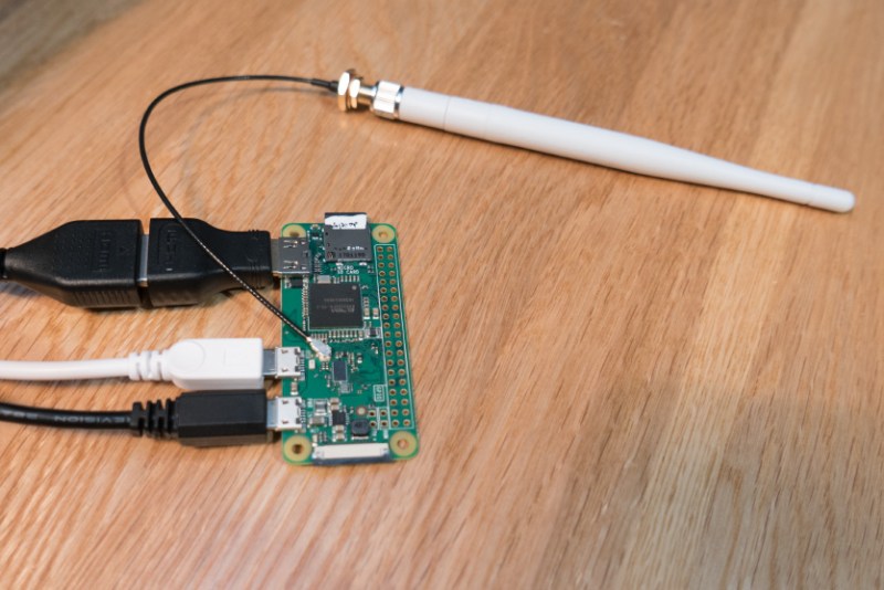
Putting a complete WiFi subsystems on a single-board computer is no mean feat, and on as compact a board as the Zero W, it’s quite an achievement. The antenna is the tricky part, since there’s only so much you can do with copper traces.
The new Raspberry Pi Zero W’s antenna is pretty innovative, but sometimes you need an external antenna to reach out and touch someone. Luckily, adding an external antenna to the Zero W isn’t that tough at all, as [Brian Dorey] shows us. The Pi Zero W’s designers thoughtfully included solder pads for an ultra-miniature surface-mount UHF jack. The jack pads are placed very close to the long, curving trace that acts as a feedline to the onboard antenna. There’s even a zero ohm SMT resistor that could be repositioned slightly to feed RF to the UHF jack. A little work with a soldering iron and [Brian]’s Pi was connected to an external antenna.
[Brian] includes test data, but aside from a few outliers, the external antenna doesn’t seem to offer a huge advantage, at least under his test conditions. This speaks to the innovative design of the antenna, which [Roger Thornton] from the Raspberry Pi Foundation discussed during last week’s last week’s Hack Chat. Check out the archive for that and more.
Thanks to [theEngineer] for the tip.


Usually the best part about an external antenna is that you can position it at a place which has a stronger inherent signal. That test antenna doesn’t look very high gain either (nominally 4-6dBi), external antennas could let you use up to 24dBi or so.
last week’s last week’s
So you’re saying it’s an article from 14 days ago for a device that was released 8 days ago???
Am I the only one who read the article? Read the 2nd to last paragraph (near the end).
The point of an external antenna is that it is external. In free air, PCB antennas can be very good. Put them in a case, and not so much…
Finally somebody pointed it out. I will be enclosing Zero W in metal case, so I’m glad the first step in that direction were already made.
Also attaching meters of thin coaxial cable won’t help the gain much… Make it as short as possible. I added an external antenna to one of those miniature WiFi USB sticks and got gain in the ~8dB area. Enough to make the OctoPi in the basement connect to my home router \o/.
And here I am, finding the fact that they managed to move the teeny, tiny resistor the most impressive bit. I can effing barely see it if I stick my nose against the board! I have no idea how to move it around successfully o_o
Convex lenses are your friend
that 1 lens from in front of an old video camera’s dinky CRT viewfinder has served magnificently
more than that which can be said for this comment function, oy
I’m more interested in how to de-restrict the existing antenna/restore power output:
Gordon explains: https://www.raspberrypi.org/blog/raspberry-pi-zero-w-joins-family/#comment-1271941
And Gordons reply when someone asks how to de-restrict is even better:
>Really, you want me to explain to you how to break the terms of our certification with the FCC? Let me think about that…
>No
Wouldn’t call hack to solder an antenna connector on a ready pad. ;)
Although judging by the capacitor he had to move, the ufl was placed for testing the antenna, not using an external antenna. If it was intended for an external antenna then the capacitor would have needed moving 90 degrees, not 45 degrees (the two possible capacitor placements for this board connect the chip to the board antenna or the ufl to the board antenna)
It’s not a capacitor, it’s a zero ohm resistor….or jumper…
Just remember: Durability: 30 cycles
Shame the FM receiver isn’t broken out.
“[Brian] includes test data, but aside from a few outliers, the external antenna doesn’t seem to offer a huge advantage, at least under his test conditions.”
WRONG HackaDay! Being able to break-out the antenna connection is the pure definition of a “Hack” – it allows you to use different antennas with different gain/directivity etc.
I had good luck with a parasitic antenna, just a loose piece of wire positioned near the resonant cavity triangle. I suppose that the length is critical. I used a length about 4-1/4 inches long and that greatly improved transmission speed. I also found that the same effect can be gained with a USB WiFi adapter, whether it is configured or not. (I wanted to be able to access the WiFi network and optionally provide a WiFi hostspot.)
This is an old post but hopefully you’re subscribed and will get a notification. Can you explain more about your parasitic antenna / passive radiator hack? How long a wire to use and how to position it relative to the pi zero board?
i want to put a 10mhz piece of wire there….. i am a ham radio operator.
About to do this. I can just use a jumper wire for the 0 ohm resistor correct? No need to be super meticulous with the small resistor, just pop it out and replace with a jumper?