[Alberto Piganti], aka [pighixxx] has been making circuit diagram art for a few years now, and has just come out with a book that’s available on Kickstarter. He sent us a copy to review, and we spent an hour or so with a refreshing beverage and a binder full of beautiful circuit diagrams. It doesn’t get better than that!
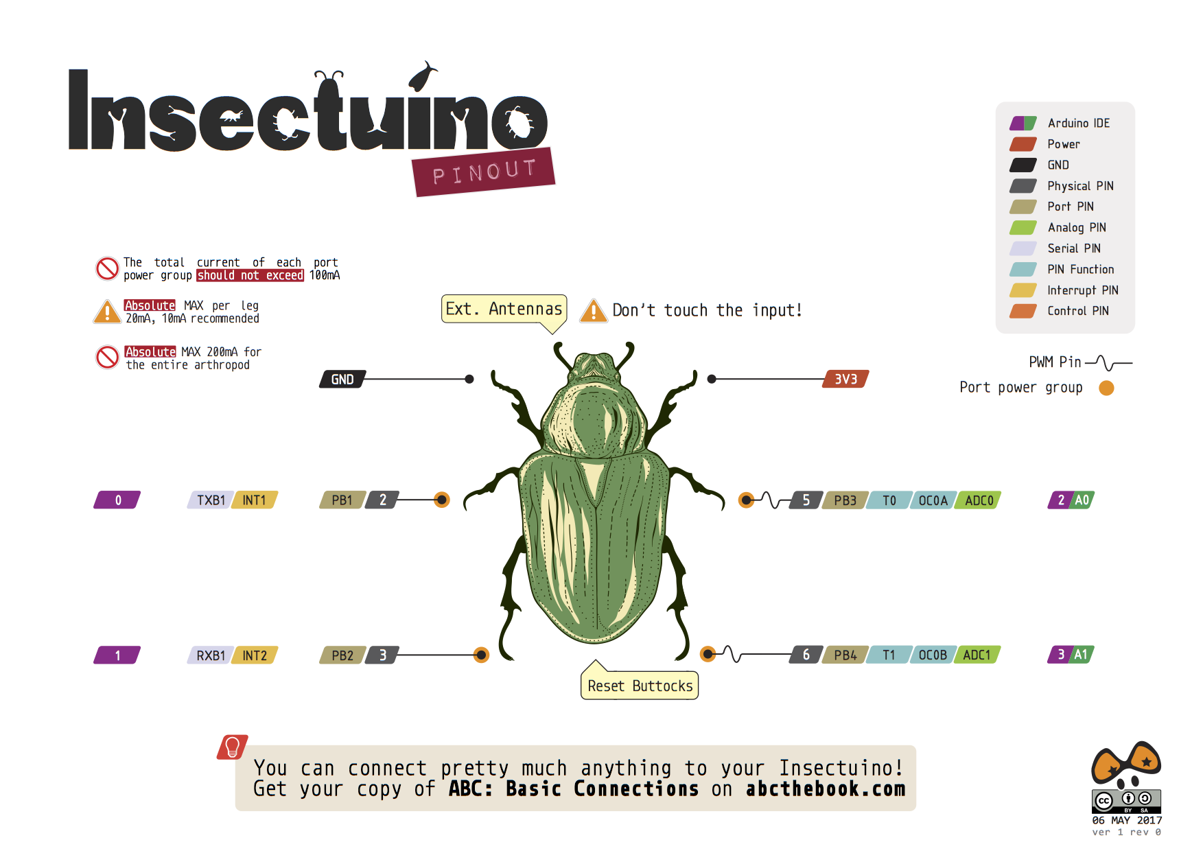
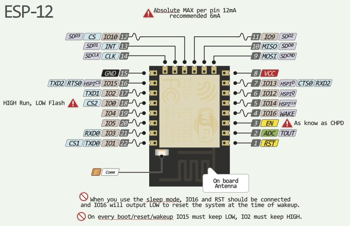 [pighixxx] started out making very pretty and functional pinout diagrams for a number of microcontrollers, and then branched out to modules and development boards like the Arduino and ESP8266. They’re great, and we’ll admit to having a printout of his SMD ATMega328 and the ESP-12 on our wall. His graphical style has been widely copied, which truly is the sincerest form of flattery.
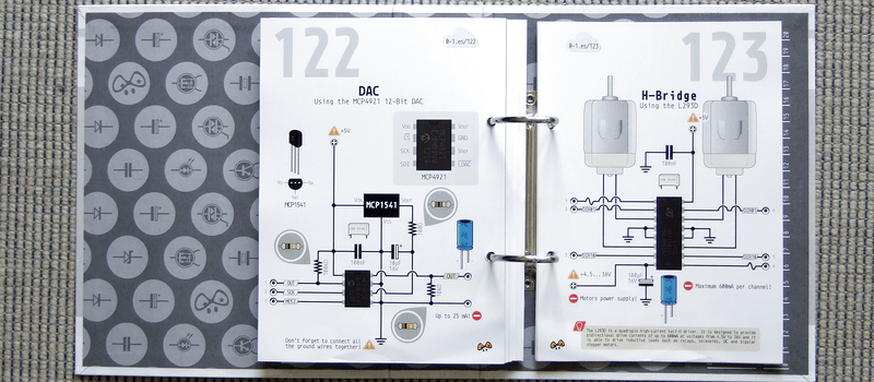
But after pinouts, what’s next? Fully elaborated circuit diagrams, done in the same style, of course. “ABC: Basic Connections” started out life as a compendium of frequently used sub-circuits in Arduino projects. But you can take “Arduino” with a grain of salt — these are all useful for generic microcontroller-based projects. So whether you want to drive a 12 V solenoid from a low-voltage microcontroller, drive many LEDs with shift registers, or decode a rotary encoder, there is a circuit snippet here for you.
 One of the things that we like most about the graphics in “ABC” is that they’re not dumbed down — they’re fundamentally just well-done circuit diagrams, but with graphic touches and extra detail where it actually helps to clarify things. This is a middle ground between the kind of schematic you use in a PCB layout program and the kind of diagram you get from Fritzing. In the former, every part has a symbol but multifunction parts like microcontrollers are just represented as squares bristling with pin numbers. In the latter, wiring up an IC is easy because the parts and pins are represented graphically, but you quickly run out of colors for the different wires, and the “breadboard” turns into a rat’s nest with a circuit of any complexity.
 “ABC” takes the middle road, using standard circuit diagram style overall, but also the nice graphic representations of the ICs and modules that [pighixxx] is good at. Is a 2N2222 pinned EBC or BCE? You don’t have to look that up, because it’s sketched out for you here. We’d guess that this attractive, but information-rich, style is a great fit for the target audience — people with some electronics experience who do not yet have their favorite transistor symbol tattooed on their forearm. [pighixxx]’s diagrams are simple, easy to understand, easy to use, and pretty to boot.
There is a planned online counterpart to the book, with further elaborations of all of the circuit setups. They’re not finished yet, but they have a lot more of the flavor of the Fritzing-style, this-wire-goes-to-that-hole diagrams. This style does work better in an online format than in a physical book, because you can build up the rat’s nest in bite-sized steps, none of which are too overwhelming. But honestly, for an advanced beginner or intermediate electronics hacker, the book can be treated as stand-alone. The web content may help the rank newbie when they get stuck.
The breadth of circuits in “ABC” is fairly wide, covering most of the microcontroller-interfacing problems that we’ve ever encountered. None of the circuits are revolutionary — they’re the tried-and-true, correct solutions to the various problems, rather than anything too hacky or clever. We weren’t surprised by any of the circuits, but we didn’t find anything that we wouldn’t use ourselves either. These are basic connections after all, and a darn solid collection of them.
To sum up, “ABC” is an attractive book in a handy binder format that would make a great collection of solutions for anyone who’s just getting started in the whole “Arduino” scene but who gets hung up on interfacing the chips with the real world. It’s a handy reference for the pinouts of a number of frequently used parts, combined with the resistors, flyback diodes, level-shifting circuits, and whatever else that you’d need to make them work. It’s what we wish our simple circuit diagrams looked like. We like it.


This type of diagram is really nice for breadboarding circuits. I always confuse myself about which pins do what and have to check 4 different datasheets to make sure I have everything right if I don’t make a drawing like these. Mi e aren’t this pretty though.
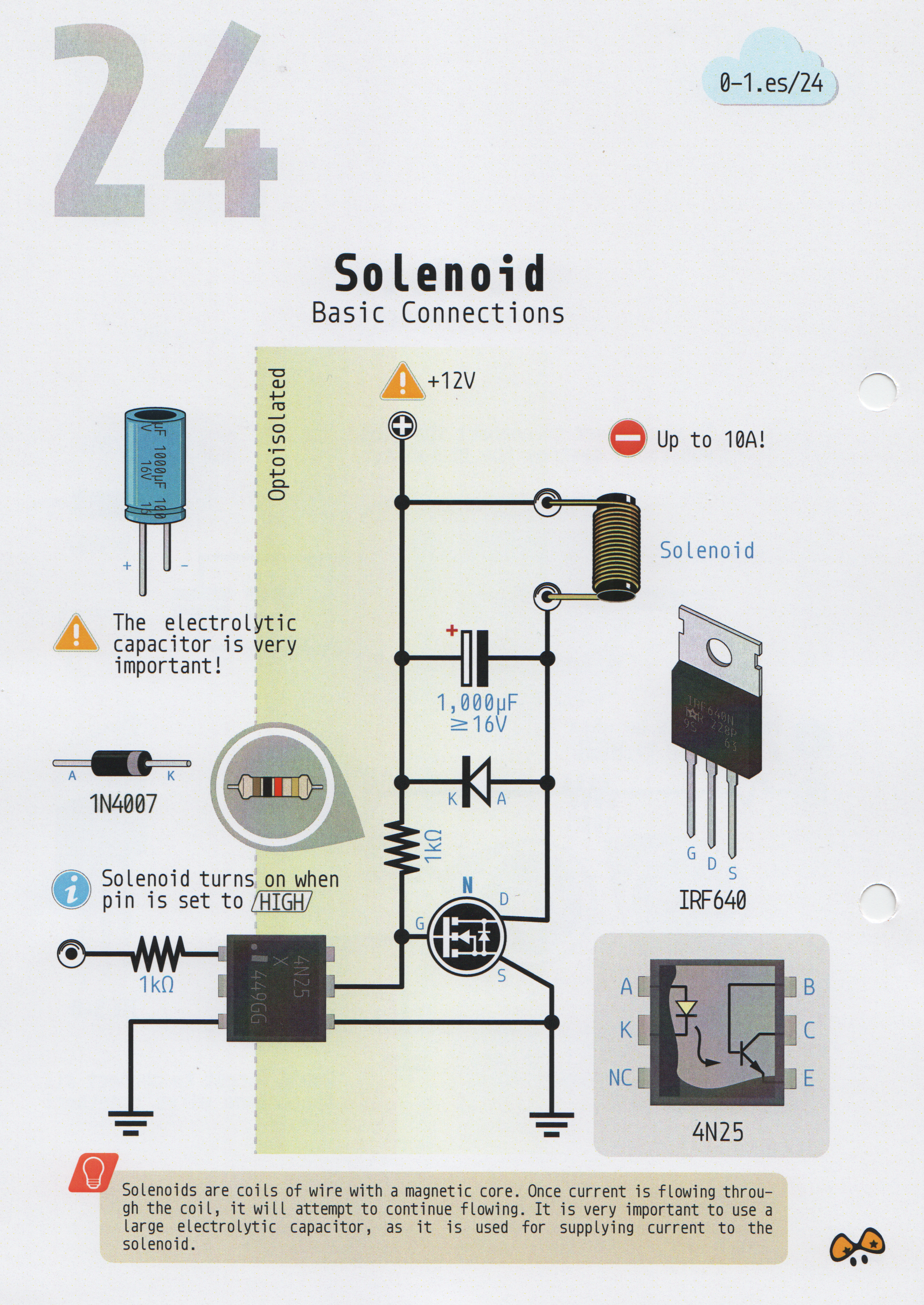
24: the opto-isolator pin 2 should be grounded, instead of pin 3 as shown.
Hello René, you’re right, pin 2 should be grounded. This is already fixed as you can see in this campaign picture (http://bit.ly/2rhd2PT). This is a pre-relase copy we printed in early April and it’s being reviewed and proofread. Thank you for pointing it out! :)
Egads! That’s already in the errata for the pre-press version. You can blame me for picking that particular diagram.
OTOH, it’s easy to pick up the mistake b/c of the inline chip pinout diagram.
My bad.
Page 24, the capacitor is also on the wrong side of the inductor.
Should be on the supply side.
As wired, when the MOSFET turns on, it will charge the cap. ;)
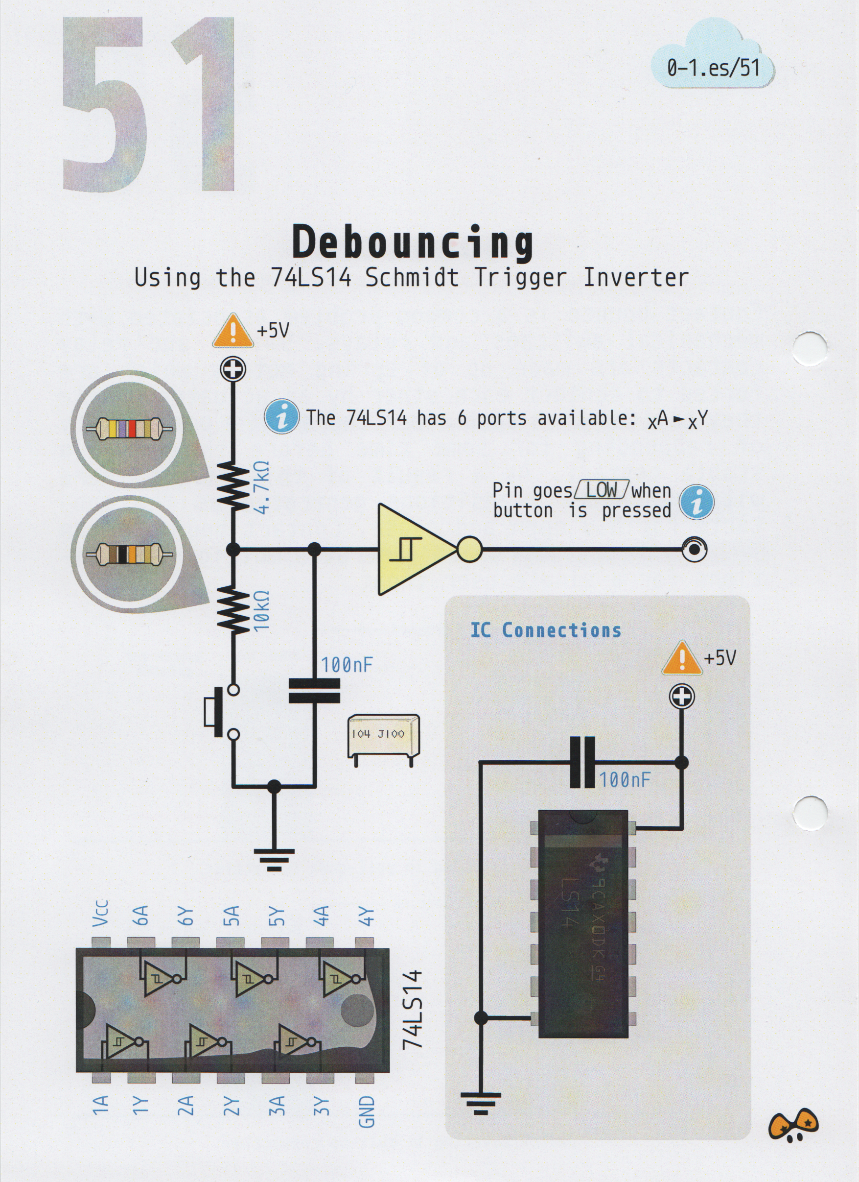
Perhaps I’m wrong, but this one looks strange to me https://hackaday.com/wp-content/uploads/2017/05/abc-51-debouncing_01.png
1, “Pin goes low when button is pressed”. Uhm, I think it’s opposite – the input goes low, so the output goes high when button is pressed. 74LS14 is inverter, somehow antiqued, 74HC14 being more modern equivalent.
2, The values of resistors should be different. The resistor in series with pushbutton is indeed good way to minimize impulse current from discharging 100nF capacitor, but the value looks way too high. 10k with 4k7 pull-up would form something like 3,3V when button pressed. While schmitt-input may actually trigger, it is marginal – datasheet states much higher values of input voltage for reliable function, I’d use something like 1k to have big voltage swing on the input and guaranteed logic zero on input when button is pressed.
3, “Schmidt trigger”. The name of inventor was Otto Herbert Schmitt.
1) You’re right. It’s already fixed in the current version.
2) Note taken! I’ll check the calculations.
3) You’re absolutely right. I take note of that!
Unfortunately the errata were found after this early April pre-release copy was printed. It’s currently being reviewed and proofread and many errata
You guys have some mad skills! Thank you guys for pointing out the mistakes! :)
Please tell me you’re not only having it proofread, but the circuits proofbuilt too – by people with the skill levels your book is targeted at?
Yes, it will be proofbuilt ;)
No, not mad skills, just basic electronics knowledge. This errors sprung out of the picture the first moment I saw them.
The “high/low” is also in the errata for the press copy. (To be fair, there are many.)
But the resistor values should work as-is? If you’re using an 74LS as in the diagram, then you get the 2.4 V threshold that comes along with it, and the 3.3 V (ish) is plenty. If you swap to the 74HC part as you suggest, you could run into trouble and would want a higher “high”.
Yes, 2,4V threshold and 3,3V is plenty above the limit – on wrong side. One need 2,4V or lower for logic zero, this circuit gives 3,3V and nothing less. With 1kOhm-ish you are on the safe side with LS, HC or HCT.
You need 0,8V or lower for LS/HCT to get a reliable zero. You need 2,0V or higher for a reliable 1.
That’s all great, but this circuit gives 5V as “logic 1” and 3,3V as “zero” – both values reliably in “logic 1” range. The resistor values are just wrong.
I really like it, but $83 AUD incl. shipping to Australia. Yikes.
Agreed, Price including shipping to Canada is similarly high. With that in mind I understand the shipping costs involved and I don’t mind supporting pighixxx as I’ve used his pinouts many times over the years.
Thank you guys :)
Some of you have had concerns about shipping costs for selected countries. We’re doing everything in our power to offer affordable shipping to all of you. Unfortunately it’s extremely hard to do it for some countries, considering the complexity of logistics and that the book with packaging weighs 1.2kg. :(
We believe we’re offering the best shipping rates on Kickstarter for an item of this kind. We studied it carefully, we’re based in Spain and anticipating high demand from the United States, for example, we are going to send pallets in a shipping container to New York and fulfil those pledges from there. But it’s not possible to do that for countries with lower demand.
We ship to Australia and Canada from the US and that’s the cheapest rate for a 1.2kg book with tracking, taking also into account the cost of shipping the container to the US. If we sent it from Spain, it would be much more expensive.
We understand your frustration, that’s why we lowered the price of the book from €25 to €23, but we cannot offer better shipping rates, in some specific cases the cost is higher than €25 and we subsidize the difference. :S
We manufacture locally in Spain and ship with reliable fulfilment companies. My 2013 book was made in China and shipped with China Post. It’s way cheaper but the quality of the product and reliability of shipping are not the same.
Yes, the downside of physical books. ;-)
“As know as CHPD” ?
:P
It’s an old pinout, I designed it before I had a proofreader in my team. That one in particular is already fixed.
We’re planning an overhaulf for pighixxx.com after the book is finished. Proper English, new design language, etc.
Isn’t putting a big capacitor in parallel with a solenoid a bad idea? Every time the transistor turns on it’ll have to charge up that capacitor, which will look like a momentary short circuit. Especially 1,000 uF! A small cap maybe, but the diode is mostly what you need to avoid voltage spikes.
It looks more like the cap will charge to power then discharge to power the solenoid. The momentary short may actually be intend to actuate the solenoid with just enough power to move the core and let the rest of the energy drain through the optocoupler. I’m more worried about the capacitor charging as soon as all components are connected. That diode helps with keep direction of flow but won’t help with keeping the optocoupler clear from any initial discharges due to not being reversed biased. Then again, I could be wrong.
I’m wondering how a 6 pin package could be rated at 200 mA maximum when the individual pins are only rated for 20 mA.
Shit, no wonder my cockroaches are catching on fire.
I had the same problem too, but found I’d been using too much force in pressing the reset. There’s not much difference between what’s needed to trigger the switch and what’s needed to squish them.
I just gave it a shot, my first kickstarter, €33 to the UK. I really hope it gets to its target. The great thing about this is that even if any mistakes haven’t been picked up, and from what Elliot said, they mostly have, they can just re-print individual pages.
+1. The book costs 30€ to Germany!
That’s the effect of the fucking Brexit, I guess D:
It sure does look pretty, but four-way junctions are not advised in schematics. The wire connection is not readily apparent at a glance. It requires more time to understand a schematic that uses them.
Several cad packages (Altium especially) have corner cases where a junction dot can be shown, but only three of the wires are connected. Earlier in my career, I learned this the hard way, which required a board respin.
These reasons are why I’ve forbid four-way junctions in every company drafting style guide I’ve written. Sadly, lazy app note authors use them from time-to-time, so people will have the “but TI does it” argument.
Does it apply only for orthogonal four-way junctions (easily confused for non-connection wire crossings), or for any?
I ask because sometimes there is a need for common point connection without common current path (e.g. analog grounds), and the way to depict it in schematics is to make a number of wires radiate from a single point (and PCB traces should be made similarly)
I’m a complete small electronics newb, (been following Hackaday for years however..) and I’ve been wanting to get into this stuff for as long as I can remember and just never have. This Kickstarter really piqued my interest as potential reference material to help actually get started. What say the elders?
If it gets you started you’re halfway there usually! Just overcoming the inertia is often a problem for me.
IMO this book is wonderful for beginners, those are some of the circuits that I always had to google when building stuff (still have to), and it’s hard to find a decent diagram – these ones are decent.
Where do I find the shipping-costs? Do I have to pledge first?
just click the pledge amount and you get a drop down menu with shipping costs.
Oh, okay. Will do, thanks!
Is the tool that is used to make these diagrams available? beautiful book just amazing.
I should have mentioned this in the article — the tool is hard work. [pighixxx] does these “by hand” with Adobe Illustrator or similar. It’s all custom clip art and paste-up.
Hi Elliot, its give a library or collection of this pictures? I will make my own IC schematics additional to the PDF Book that I use often: PCA9600, PCA81c251 etc.
You are sure that Alberto has use the Adobe Ilustrator to paint the schematics and Pinouts of the ABC Books?
Kind Regards
The artwork for this book looks very good and I am sure it will be of much use to all hobbyists. I sincerely wish the author and collaborators the best of luck with this project. Given that the author/artist is Spanish? I am curious as to why the text seems to be written in American with the out-of-date style of symbols eg. resistor.
I imagine that the answer will be that there are more of *them* than there are of us. But it is another reaffirmation of why so many of *us* chose BREXIT. If our European *friends* favor (sic) US English then what is the point of any pretense of Union?
I think the article is written in “American” because of the overwhelming availability of US culture. For instance, US series on the telly automatically teach people the American accent.
A bit off an odd diversion into Brexit you made there.
I think Brexit is more of a result of “the rest of the people” in the UK saying to the EU “we feel like its bringing more
disadvantages than advantages, so byebye, we’ve had enough”.
“Brexit” was a case of a few people having a clue what they were doing, and a huge bunch of idiots who thought it was about immigration. I suppose I should be consoled that at least 48% of my countrymen aren’t complete fucking idiots. Actually I am consoled by that. A bit. That feels better…
Given how fast public opinion changes in UK, Brexit might have been a 52/48 win one week and a 46/54 loss the next. Witness the Tory majority dropping by ten points in four weeks. Remain campaign were not armed up well enough to cope with the Leave campaign’s tactics. Remain brought a knife to a gun fight.
Anyhoo, I prefer the European symbols for electronics. I prefer the metric system. If leaving the EU were to mean a return to Imperial units for nuts and bolts, it would be even worse than it is now.
I really hope that won’t happen. Imperial units are so anachronistic!
Those of *you* who chose Brexit most likely have never had any contact with European people because the closest to them you ever got was in Magaluf when you got pissed 24h a day. The US exports more movies and TV series abroad than the UK and that’s how many people learn to speak English these days. Otherwise you wouldn’t hear European people with american accents because most schools in Europe teach British English, you ungrateful twats.
Awesome, backed it right away. Maybe you should have a weekly newsletter or so to tell if you’ve spotted errors in the graphics. So we can print the corrected versions at home and swap them.
This looks like it would be a great resource to add to school textbooks – I think the style makes thing a bit more apealing to those that find it hard to cross-check everything as they are putting something together
While I like good graphics (and these ones are very good), these drawings are construction diagrams and are not much instructional as to why things work. This latter information is found in true schematic diagrams where components are shown with their symbols and ICs are broken into their building blocks (thinking of OP-Amps). Please bring schematics back!
I could see interactive schematics solving that problem. Progressive disclosure as needed.
Are there any plans to do a non-binder style version? While the binder is great for personal use, I’m concerned that it will quickly lose pages if place in a library or classroom…
Again with the opto coupler that claims isolation while sharing the same supply?
What is this capacitor connected to the solenoid for? It will just make sure there is a very high current spike from the supply when you turn the solenoid on.
Actually, I don’t understand how the 4N25 is connected. It doesn’t look like it would work.
The ground appears to be connected to pin 3 (NC) instead of 2 (Cathode) in the diagram.
Aww shoot, I should have re-read the top comments again! They have fixed it.
Looks pretty awesome, I’d like to get one. Unfortunately after being burned on Kickstarter more than once, I can’t ethically support that type of funding nor that company. Looks like you might hit your goal though, so I look forward to buying one at full price when it’s finally available.
Pledged. Looks great for my son.
Wow! I’ve always been impressed with and very grateful for these beautiful pinouts, but didn’t realize they came from one source! Thank you Alberto Piganti!
For me, printing in China would have been a lot better. Shipping to Hong Kong is more expensive than the book!
Maybe after the book is released you could have PDF download version for a lower price. Would quite happily buy that and print it myself.
I still have the ABC books from the previous campaign and they have been WONDERFUL and so very very useful, already backed this one as well, for 3 books – though yes, the shipping is a bit on the HIGH side, but still looking forward to it.
Thank you all for your nice words and comments! :)
I read all your comments and took into consideration your suggestions about the circuits. This pre-release was printed before proofreading. Independent reviewers are suggesting changes and fixing mistakes, most of what you mentioned is already fixed, some other I will check.
The books will be printed on with high quality, 200gsm paper using offset printing technology, achieving much more vibrant colors and professional quality results.
ok I’m sold take my money. also I’m wondering about the actual material this book will be printed to, I love the ring binder format, but will this be something along the lines of laminated cardstock or perhaps print over solid plastic sheet? maybe laminated plastic sheet for maximum durability?
Hi timberly1, it will be printed to 200gsm sheets using offset printing technology and coated on both sides. They’re pretty durable and they look amazing! Other methods like the ones you describe would have made the book way pricer.
At least if they’re ringbound, you can take a page out, and copy it to then laminate, or have it laser-engraved onto steel sheets, or whatever.
Colored steel laser engraving would be something new. :-)
Format it as PDF and let me download it – for a lower price.
That also lets me bypass my other issue with the format: 2-ring A5 binders suck.
I keeps notes for my job, and use A5 plastic sheets to hold results.
3-ring binders, while hard to find, are *MUCH* better.
Once a drawing is a couple years old release it as PDF, free or fee. That will hook people on your product. True we would naturally like it all for free now but I think it better that we see thousands more being made for the new things coming over the years.
The example “debouncing” is WRONG. Contrary to the writing the pin does not go low, when the button is pressed, it goes to 2/3 of VCC (3,3V) because the 10k resistor is much too high.
The “solenoid” circuit contains an absolutely useless opto isolator. Both sides are connected to the same ground. It can be substituted by a simple BJT. Although that is a widespread misuse of an opto isolator.
haha good God this one is too obvious to be true. This is so disappointing, the diagrams look beautiful but they seem to be incredibly unreliable. Every single one that has been presented in this post seems to be full of major mistakes. Are they trolling us?
Elliot mentioned already that he received the book with an errata list and out of pure bad luck he showed those two pages that have errata. As I previously stated all circuits are being proofread, they’re also going to be individually assembled and tested so there’s no need to worry.
This looks awesome. I’m not a beginner in electronics, but I haven’t had much formal education in it either other than basic digital theory, etc. classes for my aerospace engineering degree. While I understand most of the theory, I quite frequently have to refer to online sources for circuit basics that haven’t become second nature for me yet. This book will be an awesome reference for me, and something that my kids can use when they become older when/if they are interested. I frequently use PighiXXX’s diagrams on his site, and am looking forward to receiving my book.
This is the first Kickstarter project I’ve ever backed, and it may be the last. I don’t often see Kickstarters that appeal to me as being worth backing. In this case, this is something that I could get lots of use out of, is high quality, and is reasonably priced (not too high, and not so low that fulfilling orders will be a problem).
Maybe you should look further into shipping alternatives. I guess I am not the only one who was turned-off after seeing high shipping cost. I got 20kg / 2m long package (HF antenna) from Spain for 50EUR so 25EUR for 1.2kg book seemed too much immediately. In 5 minutes I found calculator on correo.es and, if I haven’t made a mistake, price for sending book (1200g) to Croatia is 8.3 EUR (libros internacional tariff).
Just FYI in case there is enough interest from my country – local (up to 2kg) shipping cost in Croatia is18HRK i.e. about 2.5 EUR so local distribution could be feasable.
Hello Ivo, It’s much more complex than that.
What we charge for shipping had to be established before the campaign, and we didn’t anticipate high enough demand from Croatia (and many other countries) for sending a huge amount of books there and distributing them locally. It would only be cost effective for countries with high enough demand.
We spent days carefully planning this to offer the best rates possible. We don’t ship everything from Spain, we have to ship pallets around the world to selected countries to be able to offer competitive shipping rates for countries with high demand, and that’s only possible because many pledges were anticipated and are in fact coming from those countries.
According to Correos, Deutsche Post, USPS, etc. ring binders are not books. Books, according to them, have to be either stitched or spiral bound, so special rates applied to books are not available.
Sending the book from Spain to Croatia with regular rates (Paquete Internacional Económico) costs €30.37, and that’s just shipping costs. We don’t ship to Croatia from Spain, that’s why it’s €25, and bear in mind that Kickstarter and the payment platform takes 10% off shipping as well, that leaves us effectively with €22.7.
Such a fail on Kickstarter. After some production problems, the whole thing died. No book, money gone, no pdf to download.
Update: PDF available to backers. Physical version – promised.
Update: PDF to download available to backers. Physical version – promised.
my guess is because of a vast number of errors and multiple reprints the books are being held by the printer after disputes over who is responsible for costs of reprints. probably also a legal action between the parties and things have to move through the courts for a resolution.
Digital copy still up but physical copy not turned up and Alberto has seemingly vanished from the internet. His site has gone and kickstarter has been quiet since the digital copy came out
where can I buy or download the digital copy?