If you’ve been involved with electronics and hardware hacking for awhile, there’s an excellent chance you’ve heard of the Bus Pirate. First introduced on the pages of Hackaday back in 2008 by creator Ian Lesnet, the open hardware multi-tool was designed not only as away to easily tap into a wide array of communication protocols, but to provide various functions that would be useful during hardware development or reverse engineering. The Bus Pirate could talk to your I2C and SPI devices, while also being able to measure frequencies, check voltages, program chips, and even function as a logic analyzer or oscilloscope.
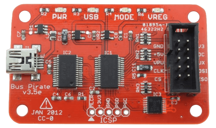
The Bus Pirate provided an incredible number of tools at a hobbyist-friendly price, and it wasn’t long before the device became so popular that it achieved a milestone which only a few hardware hacking gadgets can boast: its sales started to get undercut by cheap overseas clones. Of course, as an open hardware device, this wasn’t really a problem. If other companies wanted to crank out cheap Bus Pirates, that’s fine. It freed Ian up to research a next-generation version of the device.
But it turns out that was easier said than done. It’s around this point that the Bus Pirate enters what might be considered its Duke Nukem Forever phase. It took 15 years to release the sequel to 1996’s Duke Nukem 3D because the state-of-the-art in video games kept changing, and the developers didn’t want to be behind the curve. Similarly, Ian and his team spent years developing and redeveloping versions of the Bus Pirate that utilized different hardware platforms, such as the STM32 and ICE40 FPGA. But each time, there would be problems sourcing components, or something newer and more interesting would be released.
But then in 2021 the Raspberry Pi Pico hit the scene, and soon after, the bare RP2040 chip. Not only were the vast I/O capabilities of the new microcontroller a perfect fit for the Bus Pirate, but the chip was cheap and widely available. Finally, after years of false starts, the Bus Pirate 5 was born.
I was able to grab one of the first all-new Bus Pirates off the production line in January, and have been spending the last week or so playing around with it. While there’s definitely room for improvement on the software side of things, the hardware is extremely promising, and I’m very excited to be see how this new chapter in the Bus Pirate story plays out.
Under the Hood
While the heart of the Bus Pirate 5 is the RP2040, there’s still plenty of other hardware along for the ride.
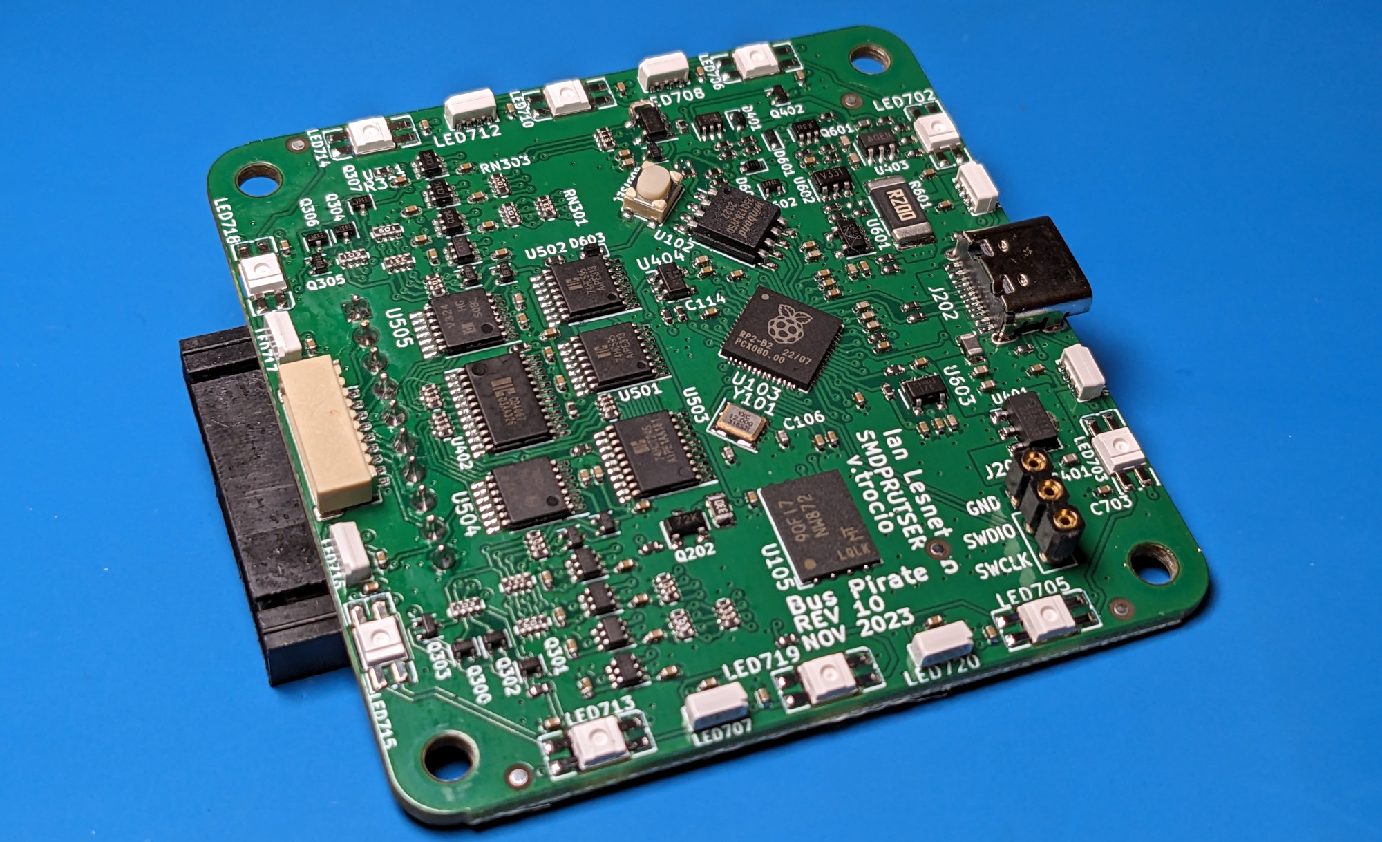
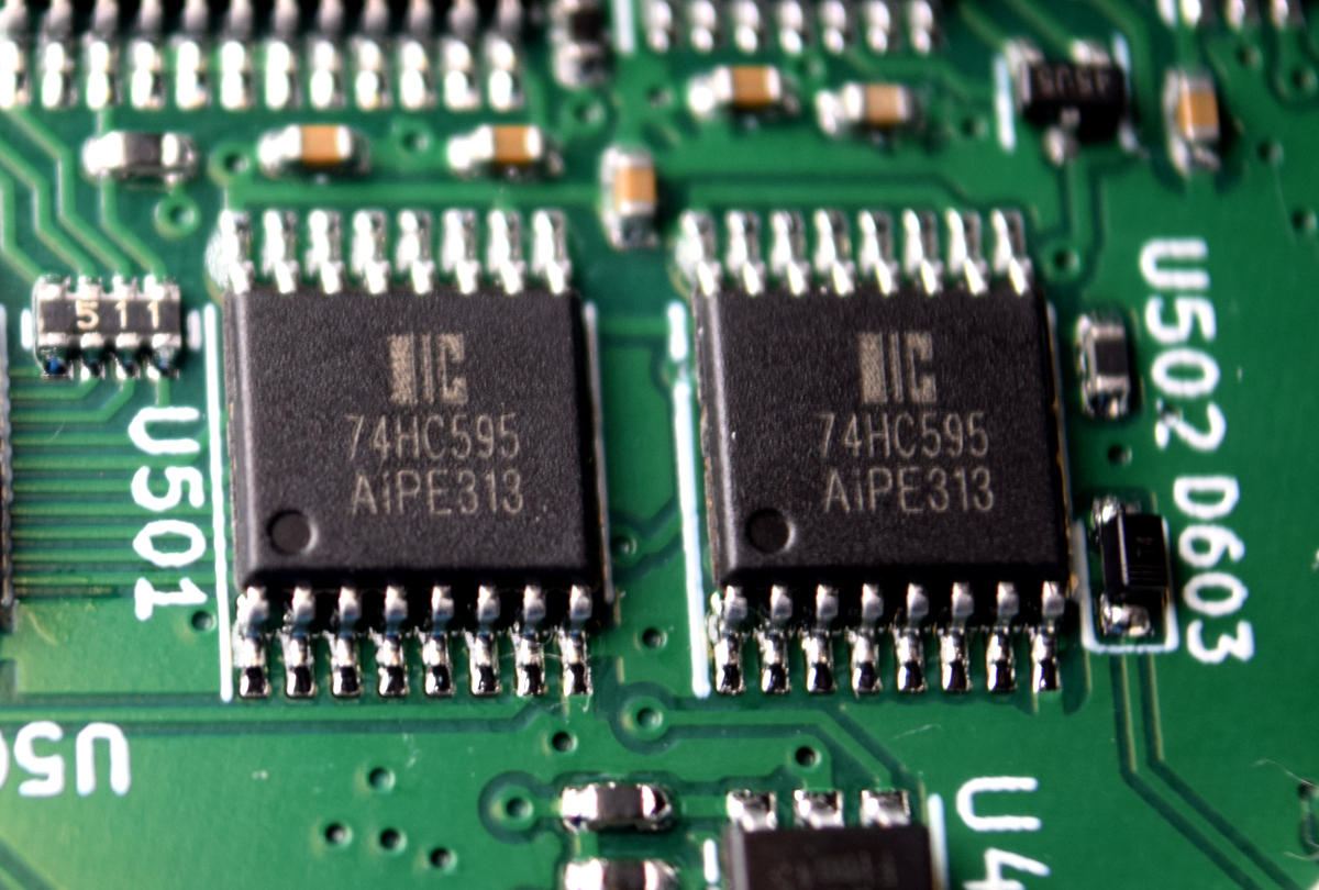
Under normal circumstances, the RP2040 would have enough I/O for pretty much any task. But since this is a device that is designed to communicate with as many things as possible, the chip actually needed a bit of help in the free pins department. As such, a pair of 74HC595 shift registers are connected to the SPI bus to provide an additional 16 outputs on the board, which are used for internal functions such as controlling the LCD backlight and switching in the 10 kΩ pull-up resistors for the I/O pins.
 Similarly, a 16-channel CD4067 analog mux is being used to overcome the fact that the RP2040 has only four ADC pins. It might seem odd that a unabashedly digital device like this would need so many analog inputs, but one of the goals for this new version of the Bus Pirate was the ability to measure voltages on each of its eight output pins, unlike the previous incarnations of the device that could only measure voltage on a single dedicated pin.
Each of the eight I/O pins on the Bus Pirate 5 go through a 74LVC1T45 bidirectional buffer, which allows the 3.3 V pins of the RP2040 to safely communicate with devices from 1.2 V all the way up to 5.5 V. It actually takes two pins from the RP2040 to control each buffer: one is used to configure it as an input or output, and the other is used to read or write from it.
There’s also a 1 Gbit NAND flash chip attached to the SPI bus which holds the device’s JSON configuration files. The volume is presented to the host computer as a USB Mass Storage device, and can also be modified from the Bus Pirate text interface using familiar commands like ls, cd, and cat. This flash storage can also be used to hold log files, firmware dumps, images to be flashed, or in a pinch, an episode or two of the Hackaday Podcast.
Programmable Power Supply
Perhaps one of the most exciting advancements of the Bus Pirate 5 over its predecessors is the programmable power supply. Earlier Bus Pirates had dedicated 3.3 V and 5 V pins that could be turned on and off, but this time there’s a single VOUT pin in the connector that can be set to output between ~1 V and 5 V thanks to the use of an adjustable regulator — the exact lower limit depends on whether your production run gets the MCP1824 or AP2127, which can be swapped depending on availability.
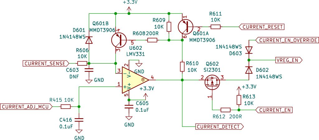
What’s more, the PSU offers real-time current measurement as well as a programmable 0 mA – 500 mA current limiter that’s implemented with only a handful of components thanks to a clever comparator circuit.
Pirating on the Big Screen
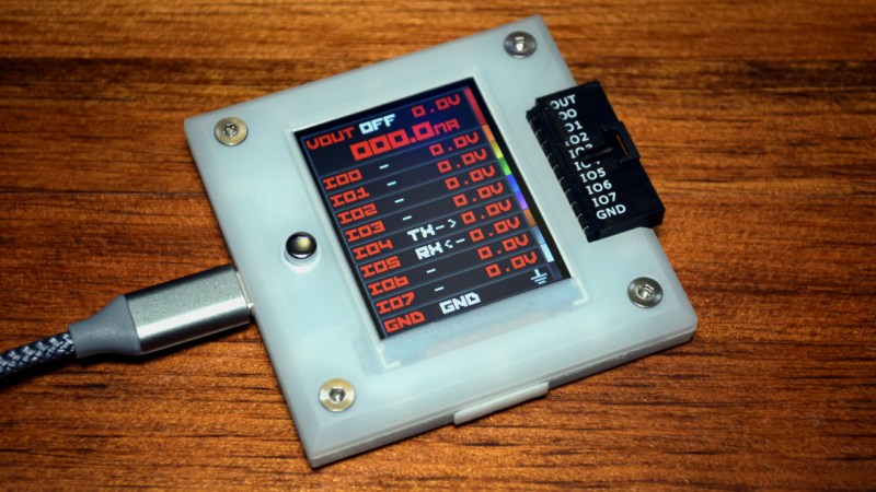
Of course, you don’t have to look inside the Bus Pirate 5 to see the most obvious new feature. The ST7789V 240 x 320 IPS LCD is front and center, and acts as a multi-purpose display depending on what the device is doing. Most of the time, it functions as a dynamic label, showing what each pin does given the current mode that the Bus Pirate is in. For example, when you switch to UART mode, you’ll instantly be able to see which pins have been set to TX and RX.
It’s hard to overstate how incredibly handy this function is. Anyone who used an earlier Bus Pirate will know the struggle of trying to figure out if you had the right pins hooked up — more often than not you’d have to go online and look up the pinout for the connector because it wasn’t always obvious what connection did what as you moved between different modes.
Beyond the pin labels, the screen also shows the voltage and current figures for the programmable power supply, and there’s an oscilloscope mode that’s in the early phases of development. Combined with the user-programmable button, it’s going to be exciting to see what the community does with the Bus Pirate 5 screen.
There are Four, Eighteen Lights!
Hackers love LEDs. That’s never been disputed by anybody. So it’s no surprise that the Bus Pirate 5 has LEDs on it, especially since the older models also came equipped with an array of status lights to indicate various conditions the device could be in. But even still…the eighteen SK6812 RGB LEDs lining the board is going to be seen as excessive to some.
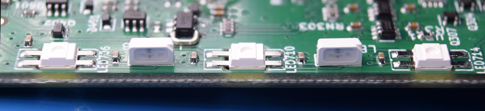
Ten of the LEDs are reverse mounted and shine through holes in the PCB to light up the front of the milky translucent case, and the other eight are side-firing variants that provide the sort of underglow effect you might expect from a over-the-top gaming keyboard or a car from one of the Fast & Furious movies.
For those that aren’t looking to turn their workbench into a rave, don’t worry. You have complete control over the LEDs on the Bus Pirate 5, with multiple options available for brightness, animation pattern, and colors. It’s also possible to simply turn them off entirely. The LED configuration is saved to the non-volatile flash chip, so whatever your choices are, they will persist through power cycles.
Personally, I think the default LED settings are reasonable enough. I don’t find it particularly distracting, and it does give the device a unique look among all the other bits of hardware scattered over the bench. That said, I also appreciate the fact that the user is given the option of either customizing them or simply switching them off, as different people will of course have their own opinions on the matter.
What does bother me a bit is that, at least in the current firmware, the LEDs serve no practical purpose. On the Bus Pirate 3, the LEDs were important — for example, you could tell at a glance if it was sending power to a downstream device. This is a feature that could have been expanded on the new hardware, with visually distinct animations indicating the various communications modes, and a flashing alert if the current limiter is triggered.
I have a feeling this is something that will work its way into the firmware at some point in the future, but it seems like a missed opportunity not to have implemented it out of the gate. If nothing else, it would have helped justify the addition of the LEDs to those who might think they’re nothing but unnecessary flair.
Console Cowboy
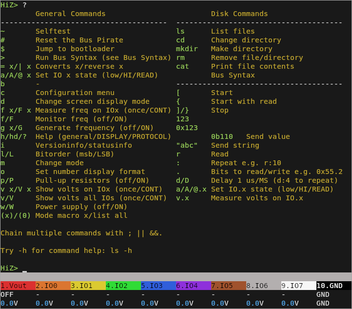
If you’ve used an earlier Bus Pirate, you’ll feel right at home with this latest version. Its serial terminal interface has gotten a refresh, now featuring colors and a very slick persistent status bar at the bottom, but many of the commands remain the same and the workflow of moving through modes and communicating with devices is basically identical. If you haven’t used a Bus Pirate previously, the interface is fairly straightforward and the built-in help functions will usually get you on the right track.
You don’t need any special software to access the Bus Pirate interface; just open up your favorite serial terminal and point it to the USB device that’s created when you plug it in. If you’re using a Chrome-based browser you can even connect to it via the Web Serial API.
As a precaution, the Bus Pirate starts in “High Impedance” mode, which disables most of the functions that deal with actually powering and communicating with devices. You’ll first have to select the communications mode that corresponds with your target device (UART, SPI, I2C, etc), and from there can turn on the power and start sending commands or performing operations.
Here you can see a basic example of communicating with an I2C device, in this case, a Bosch BMP280 sensor:
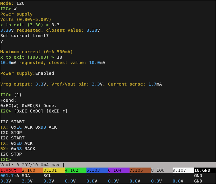
After selecting I2C mode, you enable the power supply and enter the desired voltage and current limits. You can then run the first macro, which by default performs a brute-force I2C scan. With the returned R/W addresses for the detected device, you can craft your I2C packets. In this example I’m sending a request for the register 0xD0 (Chip ID), and reading one byte of data from it (0x58).
The Journey Has Only Just Begun
Bus Pirate veterans with a keen eye may have already noticed that there are fewer commands and functions listed in the above screenshots than what they’re used to. That’s because, while the hardware side of things may have been in development for several years at this point, the software is still in its infancy. Updates are being pushed furiously to the firmware’s GitHub repository, with an automated nightly build process ensuring users always have access to the latest and greatest code.
Ian has also dropped some interesting hints on where the firmware might be headed now that he can get his head out of hardware mode and dedicate his time to writing code. There’s even been some rumblings about looking into a MicroPython variant of the firmware, which holds some fascinating possibilities. We saw first-hand how powerful the rapid iterative development process made possible by Python on the RP2040 is during last year’s Hackaday Supercon, with attendees bending the Vectorscope badge to their will in record time. That kind of flexibility on a device like the Bus Pirate 5 is honestly very exciting.
I made a conscious decision not to call this a review of the Bus Pirate 5, because quite simply, it wouldn’t be fair to pass final judgment on a product that’s still under active development. It’s an extremely promising platform, and is improving on a nearly daily basis, but anyone jumping on the bandwagon this early should be prepared for a few teething issues. That said, I have every confidence that between Ian and the community, the newest member of the Bus Pirate family will become just as indispensable of a hardware hacking tool as its legendary predecessor.


I heard rumors of an included scratch and sniff sticker that smelled like pcb factory green flooring!
That is true :) Ian made the scent custom.
Nice writeup, Tom.
“First introduced on the pages of Hackaday back in 2008”
…. yeeeah … thanks for making me feel old again. Still got my BP, still love it.
I sadly missed the link. Though I remember Ian’s writing fondly. Its dangerous prototypes that helped me discover HaD!!
Really looking forward to receiving my New Bus Pirate.
TLDR;
So that others are aware, as is often the case with development, there was a wrinkle. That understand is in the process of being fixed.
Here is the (very nice) message:
Thank you for checking out the Bus Pirate.
Your Bus Pirate order is ready to ship, but last night we found an error in batch 2. For more info please see my post in the forum:
https://forum.buspirate.com/t/rev10-batch-1-errors-fixes-replacements/165
If you’re eager to get the hardware and want to attempt a fix yourself, please open a support ticket. We can ship your order until the office closes for Spring Festival on February 5.
Revised boards will be manufactured in the days following February 19. If you want to wait for an updated board with the latest fixes, do nothing and we’ll ship it as soon as possible after Spring Festival.
It is also possible to refund your order on the order page yourself, or open a support ticket and we’ll issue a refund manually.
I’m sorry about this issue and delay, and I regret that it happened before a holiday when I can’t push things forward. Thank you again for following along while I develop the next generation of Bus Pirate.
Ian & the Shenzhen Team
***** Good Luck to Ian and the team. *****
Yeah, the BP5 I have actually suffers from this issue, you can see the LED leg that I used as a bodge wire next to “LED708” on the silkscreen.
Luckily, they caught it early and all the future ones will have it addressed.
But the colors! 😬 Why is brown there at the wrong place?
That’s literally the order for their custom probe cable. So how is it wrong? (“resistor colour code ordering” is removed from the valid answer pool, btw.)
Its come a long way since the ca 2008 serial version I still have in my bins somewhere
The RP2040 can act as an USB CDC NCM device. This would setup an ethernet interface on the host. Would be very useful for visualisation.
Do you have a link to an example project that describes such functionality?
The firmware uses TinyUSB (https://github.com/hathach/tinyusb) for its USB stack, which has support for both NCM and RNDIS for network connections.
The TinyUSB project provides a few different example projects, including this one showing how to setup a HTTP server:
https://github.com/hathach/tinyusb/tree/master/examples/device/net_lwip_webserver
It provides both RNDIS and NCM (need both to ensure wide OS support), and uses lwIP (https://www.nongnu.org/lwip/) for the TCP/IP stack. lwIP also includes various network applications, including a simple HTTP server.
Alternatively, TinyUSB also supports WebUSB, which could also be used to build a rich UI in a browser:
https://github.com/hathach/tinyusb/blob/master/examples/device/webusb_serial/
I wish it were Friday already and Tom was picking his own article to talk about on the Podcast!
The real story here is how he’s managed to make a successful product that’s survived being cloned cheaply and still be in business & releasing new versions.
Kudos anyway, BP is a great tool.
Rather somewhat completely unrelated (though referenced in the article i.e. “There’s also a 1 Gbit NAND flash chip attached to the SPI bus…”), but a question I’ve wondered for a long time– Why in embedded electronics are flash memories refered to by the number of bits they store, rather than bytes like computer hardware everywhere else ? Why not just say 125Kb ?
That would be probably because you address a serial device bit by bit so how it breaks up into words is your business. It would also make it easier to compare sizes in case of wonky architecture too I guess.
I see. I hadn’t thought about it that way/from that perspective, from which it seems to make more sense. Thanks.
It should be 128MB then ;)
Oops, yes you are correct. I’m not really used to thinking of ‘giga’ itself, just as a ‘number’, other than the more usual relation to bytes (i.e. GB).
So… What does it do?
So where is a good place to order one so you’re not getting a cheap knockoff?
If there is a link in the article, I may have missed it
http://dangerousprototypes.com/
Though I think he has now established a seperate site as well for the launch.
https://buspirate.com/
:)
I still don’t get why the documentation side of the site is littered with weird AI renders that don’t even serve anything, it just sits there cluttering up the pages. It is oddly distracting.
Thanks for the article, Tom. I now have a shinny new BP5 to play with.
If I am reading the datasheet correctly, BME280 id is 0x60, and BMP280 is 0x58. Looks like yours is a BMP.
Great catch, looked closer at the module and you’re absolutely right. Went back and changed the reference in the article.
Creeping featurism. The 3.6 version was about the prefect size and had all the capabilities I needed, and it was cheap. The new version is a monstrosity that tries to do everything at once.