One of the most versatile tools on anyone’s work bench, at least as far as electrical projects are concerned, is a power supply. Often we build our own, but after we’ve cobbled together some banana jacks with a computer’s PSU or dead-bug soldered a LM317 voltage regulator to a wall wart, how will that power supply perform? Since it’s not desirable to use a power supply that’ll let the smoke out of everything it powers (or itself, for that matter) a constant current sink, or load, can help determine the operating limits of the power supply.
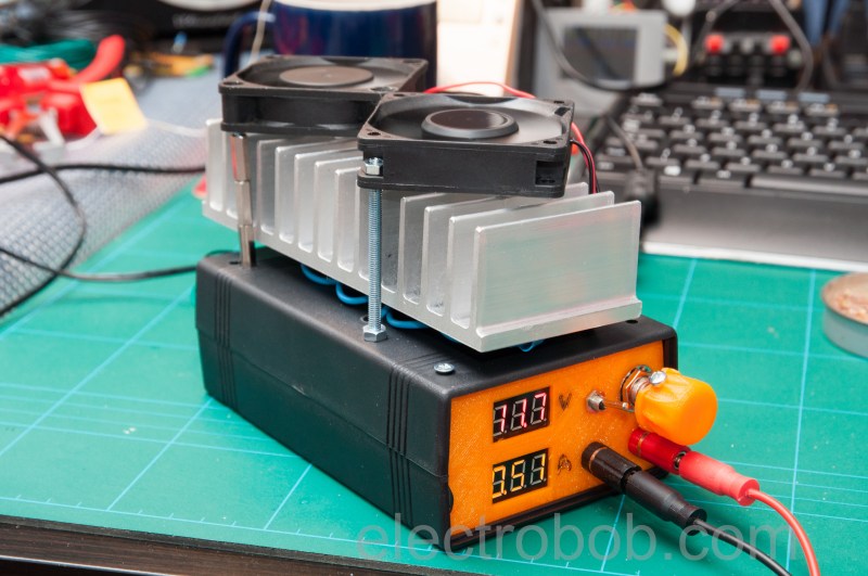
[electrobob] built this particular current sink from parts he had lying around. The theory of a constant current sink is relatively straightforward so it’s easily possible to build one from parts out of the junk drawer, provided you can find a few transistors, fuses, an op amp, and some heat sinks. The full set of schematics that [electrobob] designed can be found on his main project page. He’s also gone a step further with this build as well, since he shorted out his first prototype and destroyed some of the transistors. But, using a few extra transistors in his design also improves the safety and performance of the load, so it’s a win-win.
This constant current load also has the added feature of being able to interface with a waveform generator (an Analog Discovery, specifically) and as a result can connect and disconnect the load quickly. If you aren’t in need of an industrial-grade constant current sink and you have some spare parts lying around, this would be a great one to have around the work bench.


I’ll just leave it there: http://www.sbprojects.com/projects/ccsink/index.php
:-/
Why? Sorry, but that is a terrible way to make a dummy load unless you have a very specific application.
Without selecting a proper “Linear-Qualified” current-pass MOSFET, this design in (some cases) may actually let the “Smoke OUT”. At first-glance I do not think the Vishay IRLZ24 N-MOS pass transistor used in this person’s design is “Linear Qualified”,
Remember, most higher current capable MOSFETs are designed for switch-mode operation (they are NOT “Linear-Qualified”). In a simple example, non-linear qualified MOSFETs consist of multiple MOSFETs on the component’s internal die in parallel. So there’s little to nothing preventing one of the multiple on-die transistors from conducting before the others do as Vgs changes linearly, especially when Vgs changes slowly over time, like this person’s application.
That said, there are switch-mode/current-mode load designs possible that would eliminate most of the parts used in this person’s design (including multiple transistors, heat-sinks, fans etc.) From memory, these switch-mode designs typically fall into topologies with coupled inductive charge-storage elements (e.g. SEPIC and/or Cuk?) Some designs even work bi-directional. But switch-mode loads are typically “noisy” compared with linear designs – so it depends on your specific application which approach works best for you.
Even if you ignore that, 99% of DIY dummy loads fail pretty horribly when it comes to loading outputs driven in PWM, and those are extremely common nowadays…
this one is not in the 99%
IRLZ24 is pretty good for linear operation. You can tell from the datasheet details (SOA, “Ease of Paralleling”)
Hotspot is not that much of a problem since they are thermally coupled and MOSFETS tend to conduct less when they get hotter.
And I’m just sitting here with my Siemens and Gossen Konstanter 34 G 80 RU 4, thinking about where to put this two heavy (14KG each) power supply…
An alternative current sink with even less parts: solder some “large” resistors in parallel and/or series, to get the needed resistance. Solder on two thick wires, and dump the resistors in a bucket of water. (only for relatively low voltages, but can sink a lot of heat for a long time, depending on the size of the bucket.)
I have a large resistor bank for this purpose, but note that a resistor is not a constant current load. When testing batteries, the voltage drops, and then so does the current…
No jaap, A resistor or resistors as a load are not the same as a “constant-current” load.
The article missed the point – this is not necessarily designed to simply load a supply with some current. It is designed to be controlled by the analog discovery and monitored at the same time – so you can f**k with the supply you are testing (like loading it with a 1% duty cycle at 1 MHz) and observing the effects.
So you can measure the dynamic characteristics of your power supply and test things like stability and noise.
I tested a power supply with it here http://www.electrobob.com/peaktech-6225a-review/