Museum exhibits are difficult to make, and they’re always breaking down; especially the interactive ones. This is a combination of budget, building a one-off, and the incredibly harsh abuse they take from children.
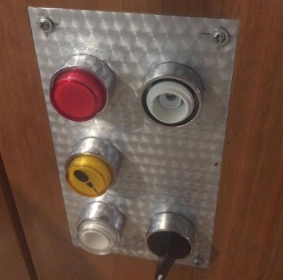
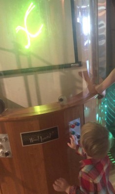
My first exhibit is an interactive laser show that turns waveforms from music into laser patterns, and different types of music have very different patterns. I knew from talking to the museum staff that industrial buttons were a necessity, but it turns out that industrial buttons are made under the assumption that tiny creatures won’t be constantly mashing, twisting, and (ew ew ew) licking the buttons. After a while, the buttons (and poor knob) were trashed.
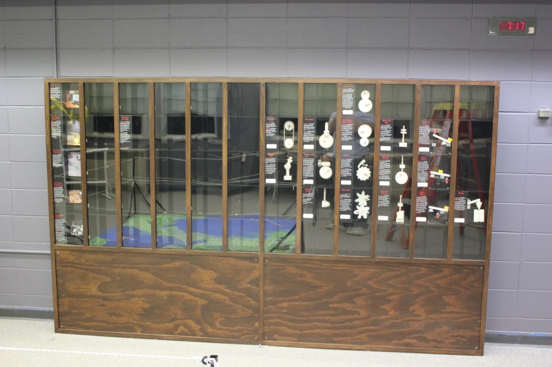
The second exhibit is also interactive, but in this case it’s just a simple button that turns on a thing for a while, then shuts it off. You can read more about the Periodic Table of Motion on the project page. Here I thought; let’s use capacitive touch, put the sensor behind two layers of acrylic for protection, and then there won’t be any moving parts to break. I built a bunch of units, tested it for weeks, then installed it. Instant failure despite my diligence.
Something is different about the installation from my test environment. It might be the second layer of acrylic contributing. Maybe it’s the power supply and a strange ground issue. Maybe the room’s fluorescent lights are creating an electromagnetic field that is interrupting the sensor, or the carpet is causing static buildup that is somehow causing the midichlorians to reverse polarity and discharge through the base plate of prefabulated aluminite. In some of the cells, the button doesn’t work. In other cells it is extremely sensitive. In one column of the table (columns share a common piece of acrylic among 5 cells), a single touch will trigger all 5.
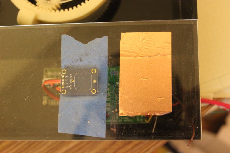
The circuit is an ATtiny with a 2.2M resistor between two pins, one of which connects via a short wire to a soldered connection to a piece of copper tape on the underside of an acrylic piece. The ATtiny is using the capsense library, which has features for automatic recalibration. Because of the way it is installed, I can’t reprogram them to adjust their sensitivity while inside the enclosure, so tweaking them post-install is not an option. I thought I could isolate the problem and use an existing capacitive touch sensor breakout of the AT42QT1010 hooked up to just power, but it had the exact same issue, meaning it’s either the power supply, the enclosure, or the room.
There are three paths I can go down now:
- Find the problem and solve it
- Switch to a photoresistor
- Petition Hackaday for a better solution
Finding the problem and solving it will be a long and difficult path, especially since the museum environment is somehow and inexplicably different from the test environment. The photoresistor option has promise; when the user puts their hand over the paper button the light level changes. Some early testing indicates that it is easy to detect instantaneous change, and a trailing average and adjusting threshold make it robust enough for changing lighting conditions throughout the day. Further, it’s a simple change to the code, and the existing circuit board will accommodate the adjustment.
As for the third option…
What have you done for child-compatible touch interfaces that are robust enough to handle uncertain environments and harsh abuse? What buttons, knobs, and other interactive elements have you used?


In the technical museum in Vienna they use these aluminum vandalism-safe buttons that have very little travel distance. either they hold up really well or they are changing them regularly. I never noticed a broken one so far ^^
Yeah, they’re expensive, but the kind of vandal-proof metal buttons you find in elevators and door intercoms, would be my choice. No option for graphics, though.
They’re only US$5 each in unit quantities. Illuminated ones are twice that. Digikey link to vandal resistant pushbuttons with flush buttons: goo.gl/3UoG8s
You can etch em.
Nthing this. Industrial != vandalism safe, and what you need here is vandalism safe. They’re not that expensive, but are designed so you can’t fuck with them from the wrong side of the panel.
Yep Araldite-Epoxy in a button or switch makes for a bad day even better Glue a coin in with it.
Epoxy and a wrong key in a lock broken off.
Coins epoxied over a lock or next to or inside hinges doors don’t close.
Not all kids sniff that glue some use it..
On some public WCs (Donauinsel, Vienna) they used “vandalism safe” piezo buttons for flushing and water. Unfortunately I have already seen destroyed ones. But they are outdoors, stones are in reachable distance (below), it is unsupervised and there is a high occurrence of drunken people.
So they could be child safe.
I used one too, It’s pretty disturbing because it’s a switch that you can’t push, but you still need to tap on it to use it. If you’re too gentle and just put your finger on it like a capacitive touch button, it wont flush. The other disturbing thing is that it looks pretty much the same as the contactless detectors also used on public wc.
(Well, flushing is getting complicated, ladies)
Relative humidity of the museum is likely lower, increasing the effect of electrostatics on your enclosure. Combine that with shoes, walking, and a large waxed floor and you will have issues.
Arcade buttons are a good option. The microswitches they contain are good for 1M cycles, and are inherently protected from all but the licking. :) Mounting them horizontally will mostly solve that.
Given you have isolation via the plexi anyway, you could try alternately floating the ground/grounding. This would allow the charge accumulating on the panels to equalize to the ground potential of your micro. If you float the ground, put a neon lamp across the earth ground/equipment ground to drain the charge periodically.
What do you think will happen when that neon lamp triggers?
That was a rhetorical question, but I’ll answer it, anyway… They will trigger. Floating grounds, semiconductors, and ESD are a bad mix.
Yep. One false trigger every now and then in exchange for normal operation most of the time.
He’s built a nice capacitor here which is likely saturating his inputs.
It may work, it may not, but at least I’ve presented a theory for the cause and a potential solution as he requested.
What about using a driven shield for the cap. sense?
Industrial buttons seem to be good for high usage environments. Just because they are industrial buttons doesn’t automatically mean they will not immediately be broken though if there are easy ways to do so. Any that can rotate a few turns and be removed will quickly be rotated a few turns and removed.
I too vote for arcade buttons, they are specifically designed to take abuse and are inexpensive and easy to install and cannot (easily) be rotated and partially removed. Some even light up as well, if that is a design constraint.
I also had good experiences with arcade buttons for museum exhibits.
Me too. We have other stuff that breaks, but I figure if any can hold up for a year on the museum floor, it’s good enough. The buttons we use do that. We buy em from suzohapp.com
Also arcade buttons are designed to be serviced and come with replaceable parts so if the switch is the failure point you can swap it out with removing the entire button assembly.
What you want is a vandal resistant switch, as seen on elevators and crossing lights.
https://en.m.wikipedia.org/wiki/Vandal-resistant_switch
I have also had luck building my own using IR break beam sensors (the u shaped ones) to detect the ends of pushable metal rods, can build that setup really beefy.
Google Vandal-resistant switches…
You will see them on automated banking machines.
I tell students to imagine this guy using their stuff on a bad day:
https://upload.wikimedia.org/wikipedia/commons/thumb/f/f1/SD_Zoo_Orangs.jpg/220px-SD_Zoo_Orangs.jpg
Not too far from reality. I saw few years ago in San Diego zoo, what i supouse was a kind of communication experiment between human and apes, composed of arcade push buttons of different color and lights!.
Why bother with the acrylic? Put a nice, solid metal plate on the front for each option and connect the touch sensor to that. Providing the case it is attached to is an insulator then it should be fine, and you can dial the sensitivity down.
Each cell is 9″ square, with the left 1/3 reserved for the description and electronics behind it. The description sits on top of a piece of acrylic with the copper tape sticking to its back. I suppose I could use a piece of metal instead of the acrylic piece, but that’s a lot of metal, and the cells sit on top of each other, so I’d have to put in some kind of insulator to prevent them from affecting their neighbors. The front acrylic covers the whole column because we don’t want kids putting their fingers into the gear mechanisms. Do you think making the touch area bigger would solve the problems?
Is there space below the description? Bolt the metal plate below the description and connect one of your bolts to the ATTiny directly rather than the copper tape. Job done.
Harken back to the days of yesteryear, to the earliest touch controls on microwave ovens. I recall at least one model with a keypad composed of recessed divots with a metal ring around them. I assume there was some sort of contact in the bottom of the divots, which were sized such that it was practically impossible to apply a fingertip without bridging the ring and the bottom of the divot. No moving parts and the rest of the microwave was built to last 50+ years so they should have another 20~30 years yet before they’ll quit, if then. ‘Coure microwaves in the 1970’s cost a pile rather than $50 so they had to be built very durable.
I also assume that the keypad was extremely well isolated so there was no chance of mains current getting to the keypad – unlike the one featured recently where the microsecond shorting of the blown lightbulb allowed mains current to blast through the control board and jump to the keypad switches via the plasma flash of a couple of vaporized PCB traces.
I don’t know if metal plates are going to fix the problem but if you do decide on using metal plates them it may be easier to just use some blank single sided FR4 PCB material.
I would use Elevator (Lift) buttons.
They have to put up with the same conditions. ;)
Or arcade buttons? They see a lot of abuse as well.
Yep – those Happ Controls buttons are ugly as sin, but have been the cheap, durable go-to solutions for museum interactives for the past 40 years.
No no no…
You need MORE static electricity.
THAT will at least deter button-licking!
Brass has a terrible taste (IMO), maybe the buttons should be brass…
I would add about 9V AC to it as well. fingers will not notice but a lick and it’s ZZZAP!
Brass also has a natural antimicrobial effect. Brass probably wouldn’t look good very long, though.
Whoops, hit report instead of reply.
Brass would likely look great. The constant use would continually polish the faces while the rest would develop a nice patina. Look at an old brass doorknob.
Nice.
The AT42QT1010 will likely be the better bet, since the capacitive sense are is much smaller. On the Arduino, you’re sensing not only the copper tape, but all the wire leading to it.
Try putting a decoupling capacitor across the AT42QT1010, right at the base of the board. Maybe a diode on the board’s output line as well, in case something is causing interference through there.
Did the test environment involve the acrylic sheets, similar in size to the ones in the final installation? Plexi can generate static electricity, and a larger sheet could contain a greater charge. (Maybe the two sheets are forming a capacitor??)
Did the test environment have the full-length runs of wire that the final version did? This has bitten me on capsense installations before. Any long wire is an antenna, and capacitive sensing is hugely sensitive to these fluctuations.
Could you give us more info about both the test rig, and the deployment environment? As much as you can about both.
You are quite possibly correct with the acrylic sheets and the wires.
For wires, each cell is self contained, with standard PC power supply connectors. They are powered with a normal ATX power supply, and I made cables that split one connector into 5, so that each column gets power to each cell in a star network. The cables can get long, up to about 2M, but they are only handling 5V and GND. Though 12V is routed, none of the cells are using 12V. This was the same in the testing environment, though, and using the same ATX power supply, plugged in through a surge protector. The wire from the Arduino to the copper foil is a consistent length, about 3 inches. It is soldered onto the back of a piece of acrylic. The front of the acrylic (9″x3″) has the description graphic pasted to it. During testing I would put a second piece of acrylic on top to simulate the installation, though it was much smaller than the actual piece. The installation has a single piece of acrylic for each column 9″x45″, so yes that is one difference from the testing environment. The whole thing is like a giant Connect 4 board made of wood, with acrylic columns protecting the cells behind.
Carpet, acrylic, low humidity, and people wearing synthetics.
There all practically Van de Graaff generators.
Had a similar problem with buttons for an exhibition. As it turns out buttons for casino slot machines are made to be bash resistant and are made in all shapes and sizes. There are light up versions and buttons as big as the palm of your hand.
Use a Makey-Makey attached to a simple metal plate?
I would use an infrared sensor and diode, they are impervious to electromagnetic fields and are well protected under a layer of glass. If it’s acrylic then my fear is it will get scratched and the light will bounce off and trigger the thing, so thick glass and a detection by change not by level algorithm are recommended.
If you run the IR LED at a certain frequency and then pass the output of the sensor through a high pass filter you’ll avoid interferences with light, so it should work for a long time. Vitro ceramic hobs use IR below the glass too and they last a lifetime.
If you want to use a mechanical button I would add a IR switch to a metallic mechanical switch, combining a robust mechanical part with the durability of an IR sensor.
Also, don’t buy buttons from china.
Try Piezo electric switches, as they are designed for harsh environments and don’t really have any moving parts. Since they are screw-in, I would recommend using thread locker to make sure they cant easily be unscrewed (not that the front of the button has much room to grip).
Could just try sticking a piezo disc to the other side of the acrylic and tuning the sensitivity appropriately.
That was exactly my aproach. Piezo tap-sensors are unbreakable and they work like a charm if properly spaced.
I can commiserate having built ‘zibbits at San Francisco’s Exploratorium (long ago). I once called a toggle switch mfg to ask about MTBF and was told 500K operations, to which I said, “That will get us through about 2 months…” — we did put a counter of some switches just to see. I did make an early version of touch interface which I (think) was just high-impedance CMOS inputs that pick up noise when touched (or vice versa, can’t remember).
But one thing that comes to mind just now is, are the touch plates mounted on acrylic? That may make them static sensitive. Can you try some other substrate, or maybe a grounded backplate?
Yes, they are on acrylic. It was readily available, cheap, flat, and easy to laser cut with no finishing steps required. That said, if it’s the cause of the problem, Maybe I should consider a different material. I imagine cardboard might work just as well.
have you tried using any other capacitive touch sense solutions? I’ve used the Microchip MTCH102 in a project and had success with it. It has an active ‘guard’ feature should help improve performance.
Use Arcade buttons, they are specifically built for kids and 200 pound gorillas smashing them all day, and in case of failure they are relatively easy to replace.
If you need a “i will drop my strawberry smoothie in here and see what happens” resistant button, try using the fancy piezoelectric buttons that they are selling online, or build your own for cheap with a piezo and some pvc end caps (there is a nice tutorial somewhere, i can’t find in my links)
If you are going for the “no moving parts” option, try using a sharp narrow proximity sensor (GP2Y0A21) behind the acrylic. People in the post will say “overkill” or “its working distance is 10-80cm”, but they work perfectly if you use them as a trigger,
They are cheaper than an industrial button, easy to calibrate, and they add some immunity to external sources of light.
I work in the Exhibits department of a Science Centre. Arcade buttons to last a little while but they do need periodic replacement. Happ makes two different styles. The better ones, have the micro switch mounted perpendicular to the button travel. That way the button can travel passed the switch rather than snapping the switch or switch mounts off.
I have had good luck with these: https://www.sparkfun.com/products/11966
I have also gone capacitive but have always used conductive material. Behind acrylic (plexiglass) you need to set the sensitivity so high that you will often get false triggers. I ended up switching to optical sensors for behind acrylic applications.
Optical sensors behind acrylic have one major problem. Eventually the acrylic gets scratched to the point where the sensors no longer works. One of our current exhibits uses one of the sharp sensors to simulate a grocery store bar code scanner. The original window was made of glass and that lasted around two months. I’ve since replaced it with acrylic as it is easy for us to make replacements. (On that note I should check and see how its holding up)
The bigger challenge is mechanical stuff. Making it tough enough the kids can’t break it, but not so heavy that they can’t operate it or can get hurt by it.
Over the past 7 years I’ve installed and maintained around 20 traveling exhibits. It is always fun to see what the fabricators came up with. There is ways an interesting history of revisions to anything mechanical. There is always lots of evidence of the previous repairs and modifications.
Ball machines are the bane of my existence. They just don’t travel well and they all have so many quirks. Balls get stuck on a daily basis with most of them. We had one where the balls needed to be cleaned with acetone weekly. Another the balls would get stuck in a spot that took an hour of disassembly to get to.
Search for a “photoelectric sensor”. This is an optical sensor placed side-by-side together with a modulated LED light emitter. When a user holds his hand in front of it, the amount of reflected light falling on the sensor changes and this can be detected by synchronously measuring the modulation level of the sensor signal. The system is robust and insensitive to ambient light because the detection works based on measuring the modulation signal (which is not part of ambient light) rather than the light intensity by itself.
How about a floor mat switch (like the type used on automatic doors) they’re designed to be pressed at least once per day by every person going into a builder, and can take a lot of abuse. (Plus what kid doesn’t love jumping on one of those switches.)
If the plexi panel has a little flex, and inductive sensor (like TI LDC series) is excellent. The sensor doesn’t touch the moving element, and all the moving element needs is a small conductive piece that can look like a button, but under the surface. The lifetime is limited by the lifetime of the surface (the case) which is what you want for a museum
http://www.amasci.com/museum.html has a section on ultra heavy-duty pushbuttons etc.
Those ultra-duty buttons for pinball-flippers are currently available from All Electronics, see their “jumbo pushbuttons,” http://www.allelectronics.com/index.php?page=seek&id%5Bm%5D=pattern&id%5Bq%5D=jumbo
They also have large arcade pushbuttons with backlights, see http://www.allelectronics.com/index.php?page=seek&id%5Bm%5D=pattern&id%5Bq%5D=lighted+pushbutton but these aren’t nearly as sturdy as the concave pinball flippers.
Back in the 1980s at Museum of Science in Boston, we went through your same process: the recommended industrial pushbuttons were worthless (beaten to death in a couple of weeks.) The solution was the pinball-flipper leafswitch buttons sold in video arcade repair catalogs. Wico catalog is long defunct, but Happ still exists:
https://na.suzohapp.com/products/pushbuttons/
The old leafswitch buttons are updated, and today use industrial microswitches which go “click” when pressed.
Here are some cutting-edge sealed leaf switches, somewhat better than the above versions which employ standard phenolic microswitches: http://www.ultimarc.com/goldleaf.html
For oldschool pinball designs, you need a leafswitch holder, plus the plastic threaded pushbutton assembly:
http://virtuapin.net/index.php?main_page=product_info&cPath=3&products_id=40
http://virtuapin.net/index.php?main_page=product_info&cPath=3&products_id=41
http://www.marcospecialties.com/pinball-parts/CABP-BUTTON?VIEW_SIZE=60
I solved a similar problem requiring a rugged number pad many years ago, but it had a weakness. I used a matrix of IR LEDs behind a lexan sheet with the button outlines painted on the reverse of the sheet. Each button’s LED pulsed at varying frequencies. Placing a finger on the button face reflected the IR back to IR receivers, that went to an AT90S8515. A timer capture detected the frequency of the returned pulses and could tell which button was pressed. The weakness was that dirt on the lexan could cause a permanent false press on a button, so the face had to be kept clean.
At Exhibitology arcade buttons are our main choice for Children’s Museums.
My previous employment had me try to rejig a capacative touch HMI design, based on the Quantum touch IC’s (then Atmel QT, now Microchip).
The setup wanted to sense touch through an inch of borosilicate… Besides the point, but the solution was to impliment the Vishay VCNL-4xxx series of IR prox sensors.
I can’t recommend these parts enough. Beautiful discrimination, even with slight variance on the air gap thickness.
Definitely worth a look!
Ditch the 2.2M resistor and use the internal pullup delay trick:
http://playground.arduino.cc/Code/CapacitiveSensor
As used in the Nickelphone project:
http://discspace.org/nickelphone/
It measures capacitance based on delay, so you can have it auto-calibrate on power-on and just react to changes that are X% above that baseline.
Like others are saying, arcade buttons are ideal for this problem. They are very cheap and accessible – Suzo-Happ sells directly to the public – and if anything ever goes wrong with them, they are very easy for other people to replace.
Could someone recommend a supplier of (non-China) quality arcade buttons ?
https://na.suzohapp.com/products/pushbuttons/58-9100-L
thanks
I was building a touch-sensitive dance floor that needed to respond to people stepping on it and be reliable and to self-calibrate, since I couldn’t open it during the event. I found the Arduino capsense library to be far too unstable for my project. Too many false positives or no positive at all.
My solution was to use the Atmel Qtouch library. It worked amazingly well!
Here’s a basic standalone demo project that gets the library working:
https://github.com/jgillick/AVR-Libs/tree/master/QTouch
I did it using straight AVRC, since I didn’t want to figure out how to import the assembler library into Arduino. Here’s the page to my full project:
https://hackaday.io/project/4209-interactive-disco-dance-floor
A video of it in action:
https://www.youtube.com/watch?v=kRJaszxuQeg
To amend my original suggestion, I’m sure the AT42QT1010 you tried is using the QTouch library. In my experience, I didn’t have much of a problem with static developing on the acrylic. The thing with the largest effect was the power supply.
You could also try to use some filters to smooth out some of the noise the sensors could be getting.
As a former arcade game tech, I also highly recommend arcade buttons. They really do hold up to tremendous amounts of abuse as I have seen first hand. They are available in a multitude of colors and sizes with or without lights. Just make sure the nut on the backside is firmly attached, or else they can be twisted loose.
I was manager at an arcade and did the maintenance on the games, too. I agree 100%. It was astounding to me just how hard people would hit the buttons and the panels. At times, I was sure someone was going to break bones in their hands.
Photo Interrupter switches. No contacts to wear and electrically isolated. Depending on your electrical interface, can be much less “bouncy”, especially if you go through a schmitt-trigger gate…
1 Arcade buttons. *avoid the really big ones they tend to need a bit more in use maintenance over there lifetime.
Side note As long as you use a good microswitch the buttton is just plastic but. i’d look for one that isnt snug in it’s sheet wobble is good for this. and mount them slighttly angled down keeps liquids out.
2. if you need a matrix style use payphone buttons.
3. if you need a spinner go loose go heavy and make your own decoder. or repurpous a steering wheel from an OLDER style arcade game.
Theres others i can think of but there a biit more complex and you dont want complex for long term use eventuily constint running will ware on electronics that rely on prox sencers uv or ir lights can be buggerd up by spotlights or sun even wiith filters.
and these instolations may get moved around quite a bit over There lifetime (not the curint iinsttalation)
Good luck.
The best and smoothest arcade spinners I ever laid hands on were (in descending order) on Omega Race, Star Trek, Tac Scan. The worst? Tempest. Spinning those too fast would cause a horrible noise, shoddy bearings I assume.
The Omega Race knob was smooth aluminum with a taper and rounded edges. Make one like that and drop its bottom into a close fitting recess and nobody is going to be able to pry or pull on it.
Just saw these today for drop in limit switch replacement. Still mechanical but perhaps you could float mount this behind the acrylic sheet with enough ‘play’ in the sheet so that they would trigger when someone pushed on the sheet in the correct area. Without the electrical contacts maybe these would have a much higher MTBF. Probably a better more elegant solution exists, but they might help someone in another application.
http://micronor.com/product/mr386/
those fibre optic switches are ~350 dollars each.
An acquaintance of mine worked for a local science museum. He said that many visitors spend much of their time seeing what they can pry loose, when they are not ignoring signage. His main thought was that children should be shuffled into a room with hammers and a large block of lead, and be forced to hammer until too exhausted to lift their hammer.
In a display on food they had a full size fiberglass cow replica with a sign mounted on the back “No sitting” People would regularly pose their children ahead or behind the sign, if the kids weren’t climbing it like a playground item. I think he wanted to replace the sign with sharpened spikes, but the museum ended up remoooving the exhibit.
The same place had a giant ball run installed that was nearly purely decorative because some donor wanted their name on a museum piece. Every so often it would drop a ball, just under the size of a duck-pin ball, from about 20-30 feet up. This item was soon withdrawn from the manufacturer’s page of things they were proud of and a large portion of the run no longer ran.
How about reed or Hall effect sensors and a button with a magnet? I’ve seen this on waterproof flashlights.
Photoresistor (LDR). To kill noise, use low resistance on input lines, like 10-50 k resistor in parallel with LDR. High-Z sensors on noisy CMOS inputs are a recipe for disaster.
Put a wet cloth the size of a handkerchief on a plate in a the back and see if that has an effect. If it does then you have static issues which wouldn’t be at all surprising as the “acrylic paper acrylic” is a perfect capacitor for storing static charges. It also is capicitive coupling and cap-sense (from memory) works by capacitive shunting. Perhaps some metal tape from the outer acrylic to the inner acrylic.
If it’s a static issue then you could put conducting tape down each side of the outside panels and ground them to the 0volts of the PSU and hope for the best. A better solution may be to use piezo tap sensors as someone else suggested – a little less intuitive but potentially far more predictable.
If it’s not a static issue then convert the power wiring from ‘star’ to a ‘completed loop’ and ensure that the extra 12V/GND wires are not connected to the PSU. Add a high value cap at the PSU (5V) of about 2200uF then add decoupling caps (about 0.1uF or 100nF) to each of the 5V inputs on the circuit boards.
Personally I think that converting to piezo is the better solution but you may still need to do the above with the PSU/wiring/capacitors.
The solution is rather simple: use a switch that separates the mechanical design from the electrical design. The typical plastic arcade button exemplifies this scenario very well. You can get away with a simple micro switch because any and all brute force is absorbed by the mechanical design of the plastic button assembly. Using any switch that is designed as a single unit will lead to early failure unless it was specifically designed for vandal proof environments.
The mechanical portion should be as robust as needed or easily replaceable by museum staff so that the part that fails first is always the user end (thus making an easy fix) rather than the entire switch (requiring disassembly and potentially soldering, etc)
The most durable switch I have ever seen are on lister sheep shears like this http://www.ebay.co.uk/itm/Lister-Sheep-Shearing-Machine-2-speed-/311893401355 they are switched with a pull rope like a common bathroom light. they have a ratchet and pawl inside and lobes on the rachet turn on and off a microswitch.
This is exactly the recommendation I was going to make. Don’t expose the switches directly to the external mechanical force. If you wanted a platform that switched when someone stood on it, you wouldn’t just set it on top of a switch. The platform would be spring-loaded, with a limited throw, and would only contact the switch enough at one extent to trigger it. Seems like the same philosophy would be good for anything with kids involved.
Not that it helps much with your capacitive sensing situation ;)
For once I have something to contribute to Hackaday. I’ve been in and out of museums for most of my career, and about fifteen years of it was spent designing, building, and installing. When it comes to things like buttons and track balls, we always turned to video arcade suppliers like Happ Controls (Now SuzoHapp North America). Arcade games are designed to be pounded mercilessly, have beer and nacho cheese spilled on them, and, yes, have people lick them, and they still work.
Piezo switches are very robust, they are not cheap.
http://s.click.aliexpress.com/e/yvZZzFi
They works only in a “pulsed” fashion, so there is no way to detect a button keep pushed for a very long time. They are also metallic so probably not very tasty
The ones you linked (just the piezo element) are only $5 for 20 of them.
These ones on ebay have over voltage and reverse polarity protection built in. (assuming the two discreets are a resistor (~1MOhm) and a Zener.
http://www.ebay.com/sch/i.html?_nkw=arduino+piezo+sensor
Low voltage, low output “range finder” set, per button.
Reed switch behind the acrylic, and an epoxy coated magnet on a chain attached to the front. Hold the magnet up to the acrylic when you want to run the display. Nothing to lick, nothing to spill drinks on, and the chain can be as strong as you feel like making it, and certainly stronger than someone can yank loose.
Activating a switch with a “magic wand” seems like a neat museum piece, but the problem is that someone will steal it.
When you open anything to the public, they will treat it like a competition to see who is strong enough to break it.
If the museum would *sell* the magnets, though, that would be a really, really good idea.
It seems like capacitive buttons are usually surrounded in the same plane by ground. That would give the button a well controlled base capacitance that increases as human flesh changes the dialectic properties between the button and the ground. It looks like you just have a piece of metal uncoupled to ground. I’m guessing it works at all because the human’s “virtual ground” adds parallel capacitance to whatever that metal piece’s capacitance happens to be? I’ll bet the base capacitance is fluctuating like crazy due to the museum’s environment.
Maybe try making an exterior border of tape around the button and connect it to the microcontroller’s ground?
You may want to consider researching the differences between self and mutual capacitance sensing. This app note from Cypress goes over the details of how to successfully implement capacitive sensing in your project. http://www.cypress.com/file/114081/download
Piezo buttons, you can get them commercially apparently, or make them, lots of schematics online, they dont move, their sealed…
I just had a very similar experience with an exhibit using capacitive sensing. It turned out that a small audio amplifier was messing up the all four sensors in the installation. I never had a chance to use a scope on it, but I’m guessing that it was adding noise to the ground throughout the install. I tried a ground loop isolator, but in the end just swapped out the amps in all the installations.
I also found that the AT42QT1010 would latch in an on state, and then couldn’t get out of it. It only autocalibrates when first powered up and when it is not being triggered. We tied the power input pin to a pin on the arduino, so that we could cycle power to it if it latched on for too long, forcing it to recalibrate.
Nice application of a watchdog timer.
For the AT42QT1010:
1)Watchdog timer is a must
2)Refer to the documentation (i.e., best practices design doc and datasheet from atmel)
3)LDO voltage regulators with proper circuitry for each sensor to prevent voltage fluctuations (they are very sensitive to this)
4) Looks like you are using Adafruit’s breakouts, unless they have recently been redesigned you will need to disable the onboard LED as it is a source of interference when placed so close to the sensing plate, also the output from the AT42QT1010 is used to actuate the LED. DO NOT use the output for anything other than a trigger either directly to an input or via a transistor network.
I used these breakouts for retrofitting a walking piano to replace the original switches for our museum and can now say we have minimal interference or false activations. This was done by implementing the above steps. This is for 40+ breakouts and two Arduino megas mind you.
Elevator buttons. Those designed to withstand just about anything for a very very long time.
Oh lordy, I feel your pain. I was creating puzzles for escape rooms where people would tear EVERYTHING apart trying to find the solutions. Photosensors didn’t work well because people would crowd over them and occasionally cast enough shadow to trigger them and we had previous problems with static so we didn’t even get into cap touch (although now I see cap touch used on soda machines and gas pumps so there must be a way to get it to work.)
We had a very limited budget so getting heavy, industrial buttons wasn’t an option. Ultimately we used as few mechanical parts as possible such as photointerupters and Hall sensors (hidden inside wood doors or with magnet wands that were tied down with aircraft cable.)
Seems like the easiest solution to buttons being destroyed is to use better buttons. Maybe stomp switches like a decent guitar pedal. They cost a couple dollars each but can literally be stomped on and still work. I jump onto those regularly when I get carried away playing guitar and only ever had to replace plastic covers that make it match the stomp box.
My 78 Camaro had one in the floor board to activate brights, original buttons with over 200k on the body. Was crazy to see the bottom of the button under the car, stamped for 1978 production date and a splash guard that seemed like it was missing for awhile. That button never once messed up, always worked if you were gentle or actually stomped on it.
If you think that’s a harsh environment, you should try prisons.
A friend of mine works for a company which supplies kiosks for use in prisons.
Amongst the things they’ve had returned broken are the 1″ thick glass protecting the touch screens and half inch thick steel…
that is how we are meant to design Museums, there is a saying “if it wouldn’t survive a prison it has no place on the museum floor” my primary role for the last 10 years has been building museum interactives that last and i stick by that saying. as others have said Suzio happ are a good source, though i have seen one of their strongest joysticks sheared in half by young children (it was a good 25mm thick aluminum) also if you want cap touch and just want it to work HMS electronics is the place to go, look in the Brightsign section.
>“if it wouldn’t survive a prison it has no place on the museum floor”
Haha!
Here is a simple solution that no-one has mentioned yet. You can buy a small infra-red led and ir led sensor pair, mounted on a small circuit board with electronics, very cheaply on eBay.
As you get close to the pair, the IR led is reflected off the fingertip on to the ir sensor. The circuit detects this and raises a 1 on the output pin.
The big difference with every other solution here, is that the plastic covering it does not have to be transparent. It can be black plastic, like the end of a TV remote, that can pass infra red light but not visible light.
Here’s a pack of five: http://www.ebay.co.uk/itm/Obstacle-Avoidance-Sensor-Module-Infrared-Photoelectric-Raspberry-Pi-Arduino-/161784843105
I saw something like that when I while searching around for non mechanical buttons… only $127 each, lol. I’m certain you could make something similiar for much cheaper.
https://www.bannerengineering.com/us/en/products/lighting-and-indicators/touch-buttons/illuminated-verification-touch-buttons-vtb-series.html#all