Fail Of The Week: Museum Buttons

Museum exhibits are difficult to make, and they’re always breaking down; especially the interactive ones. This is a combination of budget, building a one-off, and the incredibly harsh abuse they take from children.

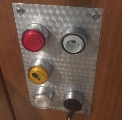
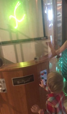
My first exhibit is an interactive laser show that turns waveforms from music into laser patterns, and different types of music have very different patterns. I knew from talking to the museum staff that industrial buttons were a necessity, but it turns out that industrial buttons are made under the assumption that tiny creatures won’t be constantly mashing, twisting, and (ew ew ew) licking the buttons. After a while, the buttons (and poor knob) were trashed.

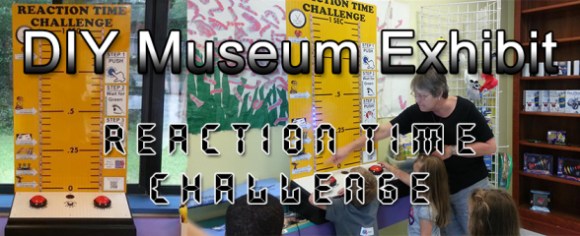
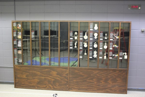
The second exhibit is also interactive, but in this case it’s just a simple button that turns on a thing for a while, then shuts it off. You can read more about the Periodic Table of Motion on the project page. Here I thought; let’s use capacitive touch, put the sensor behind two layers of acrylic for protection, and then there won’t be any moving parts to break. I built a bunch of units, tested it for weeks, then installed it. Instant failure despite my diligence.

Something is different about the installation from my test environment. It might be the second layer of acrylic contributing. Maybe it’s the power supply and a strange ground issue. Maybe the room’s fluorescent lights are creating an electromagnetic field that is interrupting the sensor, or the carpet is causing static buildup that is somehow causing the midichlorians to reverse polarity and discharge through the base plate of prefabulated aluminite. In some of the cells, the button doesn’t work. In other cells it is extremely sensitive. In one column of the table (columns share a common piece of acrylic among 5 cells), a single touch will trigger all 5.

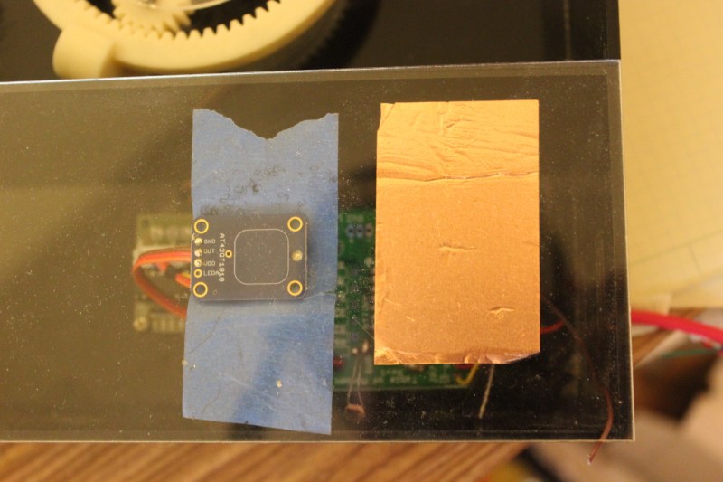
The circuit is an ATtiny with a 2.2M resistor between two pins, one of which connects via a short wire to a soldered connection to a piece of copper tape on the underside of an acrylic piece. The ATtiny is using the capsense library, which has features for automatic recalibration. Because of the way it is installed, I can’t reprogram them to adjust their sensitivity while inside the enclosure, so tweaking them post-install is not an option. I thought I could isolate the problem and use an existing capacitive touch sensor breakout of the AT42QT1010 hooked up to just power, but it had the exact same issue, meaning it’s either the power supply, the enclosure, or the room.

Side-by-side tests of copper tape+Arduino and AT42QT1010 had similar problems.

There are three paths I can go down now:

  1. Find the problem and solve it
  2. Switch to a photoresistor
  3. Petition Hackaday for a better solution

Finding the problem and solving it will be a long and difficult path, especially since the museum environment is somehow and inexplicably different from the test environment. The photoresistor option has promise; when the user puts their hand over the paper button the light level changes. Some early testing indicates that it is easy to detect instantaneous change, and a trailing average and adjusting threshold make it robust enough for changing lighting conditions throughout the day. Further, it’s a simple change to the code, and the existing circuit board will accommodate the adjustment.

As for the third option…

What have you done for child-compatible touch interfaces that are robust enough to handle uncertain environments and harsh abuse? What buttons, knobs, and other interactive elements have you used?

Reaction Time Challenge

reactionChallenge

We’re not sure where [Bill Porter] finds all of his free time, but we’re glad he’s put it to such good use by building an exhibit piece for the local science museum: Reaction Time Challenge. It’s likely that we were all inspired to love science as kids in a museum like this, and [Bill’s] contribution is already fascinating its young audience. The challenge lets two participants test how fast they can smack a big red button after a randomly-generated countdown. The time taken for the players to react is translated into the RGB LED strips, measuring how fast they managed to hit the button.

Builds like this one need to clearly communicate how they should be used; you don’t want confused children bamming around on your cabinet. First, [Bill] guts the dim LEDs inside the big plastic buttons and replaces them with some brighter ones. To keep the connections clean, he takes the cannibalized ends of an Ethernet cable and hooks the speaker and buttons to an Ethernet jack. The jack sits snugly in a project box where it connects to an Arduino. Two RGB LED strips run from the opposite end of the box, daisy-chaining from the bottom of the cabinet to the top, then back down again. See it all come together in the video after the break.

[Bill’s] museum must be pretty lucky; he resurrected the “Freeze Frame” exhibit for them just over a year ago and has done a bunch of other projects for them over the years.

Continue reading “Reaction Time Challenge”

Building A Giant Game Of Life Spinner

We see a lot of projects related to Conway’s Game of Life, but this one is Hasbro’s Game of Life. The board game company recently commissioned a giant game spinner as part of a museum exhibit. Here’s the build log that shows how it was pulled off.

The first thing to note is that [Jzzsxm] does this for a living. His company was hired to build several exhibits related to board games for a children’s museum in Springfield, MA. But don’t let that stop you from offering to help at your own local museum. We know some hackers love doing that kind of work.

The scale of the project is what makes the build really interesting. It starts with a design which can be cut out with a CNC router. First the spinner frame and numbers are cut out of MDF to verify the code. From there the design is cut in two pieces out of HI-MACS, a durable solid-surface material. Pegs for spinning the dial are milled from more HI-MACS stock. The clicker mechanism uses a steel rod as a pivot point. On the underside of the table it has opposing springs to hold it in place no matter which way the thing is spun. [Jzzsxm] mentions that it sees a lot of abuse from the young patrons, but seems to be holding up just great!

[via Reddit]

Adding Sound To Children’s Museum Exhibits

Believe it or not, the local Children’s Museum staff was happy that [Bill Porter] left this mess of wires and equipment in one of their offices. It makes up an ambient sound system for a couple of their exhibits. A movie without sound just doesn’t fully entertain, and the same can be said for these exhibits. The ambient sound that goes with a boat room, and a hospital room in the Museum really helps to snag your attention. And [Bill’s] material cost came in at just over $200 for both rooms.

He started off by purchasing a speaker, amp, and MP3 breakout board (SparkFun). The speaker mounts in one of the ceiling tiles, with the wire running to a different room where the audio equipment is housed. There were a couple of problems with this; the museum staff forgot to turn on the system, and for all of its expense this only provided one room with audio. Bill figured that since only one speaker was being used he could make an audio file with a different clip on the left and right channel, then feed them to different rooms. He also added that programmable timer so the sounds will turn themselves on and off.

This isn’t the first time we’ve seen hacks end up as museum pieces. Check out this other project that rigs up some interactive telephones.