Have you, dear reader, ever needed to plot the position of a swimming pool noodle in 3D and in real time? Of course you have, and today, you’re in luck! I’ve compiled together a solution that’s sure to give you the jumpstart on solving this “problem-you-never-knew-you-had.”
Ok, there’s a bit of a story behind this one. Back in my good-ol’ undergrad days, I got the chance to play with tethered underwater robots. I remember fumbling about thinking: “Hmm, with this robot tether, wouldn’t it be sweet to string up a set of IMUs down the length of the tether to estimate the robot’s location in 3-space?” A few years later, I cooked together this IMU Noodle project to play with some real hardware in the spirit of solving that problem. With a little quaternion math, a nifty IMU, and some custom PCBAs, this idea has gone from some idle brain-ramble into a real device. It’s an incredibly interesting example of using available hardware and a little ingenuity to build a system that is unique and dependable.
As for why? I first saw an IMU noodle pop up on these pages back in 2012 and I was baffled. I just had to build one! Now complete, I figured that there’s enough math and fun-loving electronics nuggets to merit a full article for this month’s after-hour adventures. Dear reader, let me tell you a wonderful story where math meets electronics and works up the courage to ask it out for brunch.
Just What Exactly Is an IMU Noodle?
Born into a world of commoditized MEMs sensors, the IMU Noodle is the grandbaby of modern motion capture technology. In a nutshell, it’s a collection of IMUs strung together on a flexible object to model that object’s curvature in 3D. Each IMU in the chain is individually addressable and reports back its orientation in 3-space as a quaternion. IMU data gets streamed back through a Teensy and into my PC at a healthy 60Hz clip where a small snippet of OpenFrameworks-backed code visualizes the data.
Noodle Hardware
So much of what we read on these pages gets props for being “clever.” Today though, I want to lay out a design that’s on the other side of the spectrum: in the land of all things simple. While lots of hardware projects are packed with a plethora of core features, this project has just one, copied over and over again. Let’s talk hardware.
The IMU Noodle Node:
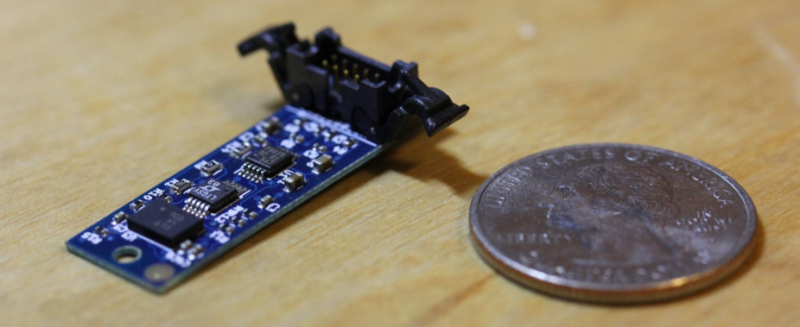
Here in hardware-land, the IMU node isn’t too complicated. It’s more-or-less just a breakout board for the Bosch BNO055 orientation sensor, with two extra tricks. First off, these boards communicate over a differential (D)I²C bus. We’re probably pretty cozy with I²C. The differential part simply re-encodes the SDA and SCL signals onto two differenential pairs, letting us extend the I²C bus over long cables.
If you’re curious about why you can’t just make the SDA and SCL wires longer, check out my brain-ramble from a couple months back.
Next off, these nodes will be sharing an I²C bus along a single cable, so they each need a unique address. To make that happen, I’m using the LTC4316 I²C Babelfish to re-encode the BNO’s address. To set the new address, I’m using a voltage divider (3 resistors) with voltages that correspond to a bit code as per the LTC4316 datasheet. (The calculations get a bit messy, so I wrote an IPython Notebook to do the heavy-lifting.)
With these two tweaks, I can now run a long ribbon cable out for a few meters and drop up to 63 IMUs onto the same cable at any location along the way. It’s clean, simple, and the only work on my end is soldering 3 unique resistors to set the address. (Note: here’s where labeling the underside of those PCBAs with their address comes in real handy.)
The Almighty BNO055
The BNO055 on its own is truly a remarkable piece of silicon. Not only does it have a three-axis gyroscope, accelerometer, and magnetometer, it also has an internal microcontroller that samples these sensors and runs an IMU “fusion” algorithm to estimate orientation.
Sensor fusion used to be a computationally expensive and technically challenging problem involving Kalman filters and well-characterized sensors. However, back in 2010, a PhD student named [Sebastian Madgwick] published a paper for a computationally inexpensive algorithm that worked at sampling frequencies as low as 10Hz and worked better than some proprietary alternatives [PDF with source code!]. From poking around the literature, this algorithm is so popular (and works so darn well on resource-constrained devices) that I’d take a wild guess that the BNO055 takes some inspiration from [Madgwick’s] work.
As far as IMU Node hardware goes, that’s it! A few years ago, this project would’ve taken countless hours of fusion algorithm design and sensor tuning, but the BNO055 has kindly offloaded the work into a $10 piece of silicon.
Noodle Math
And now for some math. Don’t sweat this one. If you can conceptualize vectors, you’ll do just fine.
Real-World Assumptions:
To convincingly reproduce our real-life noodle as a virtual doppelganger, we need to set the laws of the land. These rules are “freebies” that will help us devise a solution that best approximates our real-life constraints.
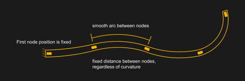
First, we’re going to assume that the distance between nodes is fixed. We’re taping our nodes down, so this assumption should approximate fairly well in real life too**. Next, we’ll declare the position of the starting node to also be fixed. Hence our noodle can curl and twist, but it can’t translate. Finally, we’ll declare that the shape between the two nodes is a smooth arc. With that last assumption, note that more nodes means a better approximation of the shape, but I’ve found that 3 nodes is already enough to fool most of us.
With these rules in place, we’re ready to start drawing.
**Actually, the distance between nodes does change when they’re fixed on the outer surface of our flexible object. A better approximation would be to mount the IMUs in the center of our flexible object, which, despite bending motion, really does maintain a constant length.
A Noob’s Guide to Quaternions as Rotations:
Ok, now for the big question. The BNO055 spits out orientation encoded as a unit quaternion. Just what-in-four-dimensional-space is a unit quaternion? A quaternion is a collection of 4 numbers, one real, and 3 imaginary. We can represent them as a tuple of four components: (w, x, y, z). A unit quaternion has a Norm (think magnitude) of 1. These days, unit quaternions have very convenient mathematical properties that make them extremely nice for representing rotations in 3D. (Aside: an orientation is just a rotation with a starting point.) Quaternions also have very well-defined rules for how to add and multiply them together.
Ok, so how do four numbers help us represent a rotation? It turns out that we can encode two pieces of information inside a unit quaternion: an axis (represented as a 3D vector) and an angle (just a scalar).
Before folks unanimously agreed that Quaternions are way better, we used to represent orientations in 3D using 3 rotations about the 3D plane’s axes, commonly known as roll, pitch, and yaw. This representation has a variety of complications. First off, the order of rotation matters. What that means is that choosing to roll-pitch-yaw, vs, let’s say, pitch-roll-yaw, will put us in two different final orientations! The next issue is a phenomenon called gimbal lock. In a nutshell, if, in our sequence of rotations, we rotate onto another rotation axis such that they both align, we lose a degree of freedom. (For a much better explanation, check out this clip.) Gimbal lock also prevents us from being able to take a direct path from one orientation to another.
Quaternions to the rescue! rather than encode an orientation as three separate rotations from a starting orientation, quaternions use just one rotation. Doing so relies on Euler’s Rotation Theorum, which, in our case, states that any three rotations about the 3D plane’s three axes at the origin can be summarized by a single rotation about some axis that runs through the same origin. Hence, rather than needing to hold onto information about three separate rotations, we just need to hold onto one, and that’s exactly what a quaternion does.
Keep in mind that, while a quaternion encodes a rotation by storing both an axis and an angle, we don’t actually plot this axis or angle. Rather we use the quaternion as an operator. Since there are very well-defined rules for quaternion multipliciations with 3D vectors, we typically start with a vector, compute a couple quaternion products with this vector and the quaternion, and get a vector back, which is the result of rotating the vector by the axis and angle amount stored in the quaternion.
The SLERP Algorithm:
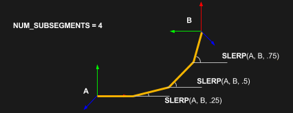
Possibly the most useful feature of quaternions for this project is their ability to provide clean interpolations. Interpolations sound complicated, but the idea is pretty simple. Imagine we have two orientations: a starting orientation (A) and a finishing orientation (B). We want to smoothly rotate from the starting orientation to the finishing orientation along the shortest path, which would be a smooth arc. What’s more, we want to take evenly-spaced steps along the way to get from start to finish.
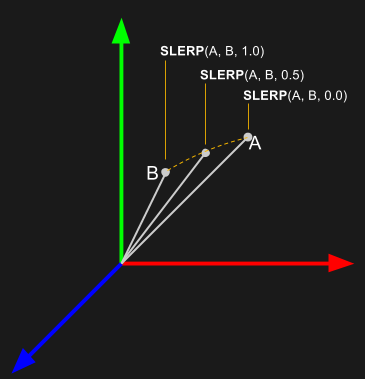
The Spherical-Linear Interpolation Algorithm (SLERP) does just that, taking two quaternions to represent our start and finishing orientation as well as a scalar (from 0 to 1) to determine how far along the path we want to end up. While the idea seems pretty straightforward, it turns out that writing an equivalent algorithm that does the same thing with rotation matrices is really hard. There’s just no clean way to smoothly interpolate from one orientation to another when our orientations are encoded as rotation matrices. If our project calls for smooth interpolations, our best bet is to use quaternions.
If we’re just getting started with quaternions, the diagram shown here can be somewhat misleading, so here’s a quick reminder. Don’t forget that we use quaternions like operators. When we use unit quaternions to store rotation information, we use them like we would use a function. Our input is a vector. Then we compute a few quaternion products. Finally, our output is a vector. Hence, this diagram doesn’t actually show any quaternions! Rather, it shows two vectors that have been rotated into the orientation encoded by the quaternions A and B.
The Noodle Doodle Algorithm:
Given our starting assumptions and a nifty way to smoothly interpolate between orientations, we’re fully equipped to draw our noodle in 3D. The algorithm goes a little like this:
Let a segment be defined as the section of length between adjacent nodes. First, divide the segment length into a defined number of subsegments.
Starting at the staring orientation, For every adjacent pair of orientations, translate a vector of the subsegment length onto the head of the previous vector (with vector addition), rotate that vector by the current fraction of the total rotation computed with SLERP, and then draw the vector.
In a nutshell, the more subsegments we draw from one quaternion to the next, the more convincing our visualization becomes.
Demo Reel
The above algorithm runs at a 60Hz clip; it’s much more fun to watch when we see the result in motion.
Magic from a World of Commoditized MEMs Sensors:
These days, our phones are jam-packed with heavy-hitting embedded sensors for making sense of our environment. Conditions like pressure, temperature, orientation and global position are all at our fingertips; sometimes it’s easy to forget just how much information about our world is being sensed from our pocket. App developers are loving these sixth-senses coming to life in our world. Heck, just imagine ride-sharing technology without GPS or video calls without an onboard camera.
While app writers and consumers are reaping the benefits of phone-tethered sensing, there’s still a rich uncharted territory that involves simply playing with the sensors themselves — outside the phone. That’s where you come in! My challenge to you, dear reader, is to chart this unexplored territory. Dig deeper and explore its limits! And, of course, if you dig up anything fun, let us know.
Finally, if you like what you see here, why not have a go at building one? PCB files, visualization code, and firmware are up-for grabs on Github.


Just watching the post animation, it looks like the mimic projection has a fixed left-most point, while the physical thing the guy with the man-bun is waving around has a moving left-most point. So all (at least 2D projection) degrees of freedom are not reproduced? Hmmm… And NO I have not read the linked stuff yet, and I probably won’t. Sorry, I’m not that interested. I just want to point out the obvious issue missing in the O.P. here on HaD (not that I don’t like the post – thanks HaD).
The left-most point does rotate, but does not translate. While it is possible to use gyros to measure translation over time, they will eventually start to drift. So you need an absolute positioning system to re-zero them periodically (like GPS, or a camera vision system, etc.). Mapping the left-most point to a fixed point on the screen and displaying everything else relative to it means you can ignore the drift. And typical applications for this (position of an arm or tentacle, for example) will have a known shoulder point relative to the body (or brain) center, so what’s shown above is perfectly adequate for that.
RTFA.
“Next, we’ll declare the position of the starting node to also be fixed. Hence our noodle can curl and twist, but it can’t translate”
Seems like a reasonable way to do it, because cheap IMUs cannot really track position very well if there is no other positioning method (like GPS) to cancel out the drift. So this uses only orientation tracking and it captures the shape and orientation of the noodle, but not its position.
Seem like the kind of thing the Vive Lighthouse is meant to solve. There seems to be some good work going on to reverse engineer the system, so you should have a viable solution in the foreseeable future.
First, that issue is discussed in the summary, you don’t have to follow any links.
Second, if you are not going to even read the summary, then STFU.
Wonder if the military had developed some of this stuff before he did? Inertial navigation and all that.
Presumably for computational simplicity, the initial position is considered an origin, and is fixed, which precludes the possibility of measuring translation. If you want to model translation, you could define a translation vector from an arbitrary reference point to the first node. In contrast to the (ideally) uniform spacing between noodle nodes, the distance between the external reference point and first noodle node will be variable.
Very cool project! I remember using Madgwick’s algorithm back in grad school for a similar project involving body tracking. Too bad the BNO055 wasn’t available back.
Noodle SLERP-ing, finally serves a purpose?
I’ll go away now.
This could close the loop on some of the tentacle builds I’ve seen, and result in an actually controllable tentacle, in the sense of actually being able to reach a desired point in space or achieve a desired shape, rather than just flailing suggestively
Let me be the first to say: VR CONTROLLER!!!
I want this on gloves, or even better, full suit.
Looks nice.