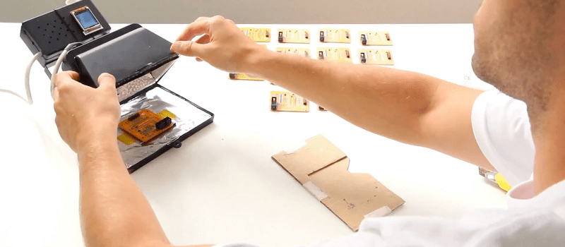
There are almost as many ways to reflow a surface-mount circuit board as there are hackers. Today, we add another method to the list. [Dasaki] converted a halogen floodlight into an SMT oven, and did so with all the bells and whistles. Check the video below the break.
We’ve actually seen the low-tech version of this hack before, but it’s nothing we would want to use on a daily basis. [Dasaki] needed to get 100 boards done, so it was worth the effort to get it right.
The floodlight was a natural choice — it’s got its own built-in chamber, and when [Dasaki] tested it out, it got up to 300 °C at 5 °C/sec and showed no sign of stopping. Contrast with toaster ovens which start complaining around 250 °C, if they make it at all. Aside from the lamp itself, the rest is standard temperature-controller fare, a SSR and a thermocouple interfaced with a microcontroller. Code is up on his GitHub.
We’re partial to skillets ourselves, but a professional halogen/IR unit is Bil Herd’s favorite. Indeed, there are so many ways to get the job done, ranging from the hacky to the nearly-professional, that you’re sure to find the reflow oven design that fits your budget and tolerance for fooling around. [Dasaki]’s halogen lamp oven looks like a worthy addition to our list.


Hmm, this might actually work without any added electronics at all, with just a timer. Of course not as fancy as controlled temperature, but it would be a very simple, cheap and compact reflow oven.
Unless your profile requires heating up from cold to 300C over a 5 second period, I doubt that would work out well at all!
Sigh, and I also cannot read. 5C per second, rather than up to 300 in 5 seconds.
Without a feedback loop, the lamp will likely go into meltdown mode…it’s not designed to have so much heat reflected back into it…
Really? What is there to damage? There’s the metal reflectors, the quartz bulb, and the tungsten element, which is already white-hot. Can’t think where there’d be harm.
The tungsten element is white-hot despite all the losses from radiation and convection… guess what happens when you reflect heat back into it…it gets even hotter.
As the tungsten gets hotter, it’s resistance rises, reducing power draw. I’m not sure how close to the edge the bulb typically runs, but incandescent lamps have a natural passive negative feedback that partially corrects for varying voltage and ambient temperature.
hanelyp: Only to a point. Accordint to https://www.tungsten.com/materials/tungsten/, at 2727 °C (3000 K), which is close to the temperature halogen bulbs operate at, tungsten’s resistivity is 90.4 μΩ-cm, while if you raise it another 1000 °C, it only goes up to 108.5 μΩ-cm. That’s only a 20% change.
5 C/second is faster than pretty much all profiles recommend. You can sleaze a half-decent reflow cycle with a slower-than-normal ramp, but that really won’t work as well as a proper soak period. But if your heating element generates a fastter-than-normal ramp, you’ve got to have some way to slow it down. A fixed dimmer and a timer might work, but at that point the electronics aren’t much more of a cost.
Great idea. Can it be inverted so that the heat comes from underneath? I like hotplate reflowing as the heat comes from underneath so large components do not absorb too much heat. Everything heats uniformly when components are on the upper side only, as is usually the case. The downside is that the whole PCB has to be heated through. You need to be careful with the max temp so as not to damage the PCB and the profile needs more ramp up time. My problem was the slow response time of even an infrared hotplate made this difficult to control. I wanted to use a halogen hotplate for better response but these were expensive and hard to find. The use of a halogen worklight looks like it could solve my problem if it can be set up to heat from underneath. Maybe a few PCB support wires or an IR transparent window would do it. Any thoughts on how to do this?
FR4 pcbs are good insulators. There is way too much energy wasted in heating a pcb from underneath. Basically no one uses hot-plate-soldering in the industry due to the horrible efficiency.
buy a flat toaster?
I bought one of these cheap when they were on sale at Walmart, apparently because the specific model was being discontinued, but anything similar could be used:
https://www.amazon.com/Rival-CKRVSK11-11-Inch-Electric-Skillet/dp/B008Q331IG
The glass lid acts as an excellent IR reflector based upon a non-contact IR thermometer reading through it. Since the emissivity of a dark teflon surface is pretty high, I used the same IR thermometer to develop a temperature profile. It turned out that a series of 30 second full on, then 30 second full off power adjustments worked great for an approximately proper length and temperature rise rate bake period with a full minute for the final, rapid temperature rise to solder flow. Cool down is accomplished by carefully removing the board shortly after solder flow. Not the ideal cool down period, but I haven’t had any problems and don’t want to expose components to any more heat than needed.
Note that I only have the need to do one board at a time which is positioned in the center of the skillet, so that’s all I’ve ever done. Temperature variations at various points on the skillet closer to the heating element would result in much different temperature profiles for each board position, so this is a hobbyist one-board-at-a-time method.
Wow, you literally “cook up” your circuit boards. :)
I use one of these in the kitchen and one for etching.
The one in the kitchen is hopeless for cooking because the mechanical thermostat has far too wide a hysteresis and there is a long thermal delay between the heating element and the thermostat sensor. So you have to keep re-adjusting the temp manually.
I also use one for etching as I etch at 70 Celsius (below boiling point) and I solve the hysteresis problem but having the etch tray suspended above the bottom of the pan and having 2 inches of water in the pan for thermal regulation by thermal mass. Even so, I let the temp stabilize over 20 minutes or so before etching. I also have a temp sensor in the water and adjust the temp manually.
So I suppose what I am saying is that when it come to temperature regulation these pans are about the worst possible.
Unless it’s really special glass, the LWIR thermopile (probably 5.5 um to 12 um or so) can’t read through it. You’re taking the temperature of the glass instead of the temperature underneath it.
https://www.newport.com/medias/sys_master/images/images/h07/h37/8798003331102/EG-pg15-8b-600w.gif
The glass is Pyrex but I have no clue what that would change.
I hope this article is joke :)
this lamp emits mostly IR waves, which means black components will heat up more than white, which will lead to not even temperature distribution on the PCB, heating board up to 300 C for 5 seconds is bad idea it will not comply with any known solder paste profile
https://en.wikipedia.org/wiki/Halogen_lamp#Spectrum
“Like all incandescent light bulbs, a halogen lamp produces a continuous spectrum of light, from near ultraviolet to deep into the infrared. Since the lamp filament can operate at a higher temperature than a non-halogen lamp, the spectrum is shifted toward blue, producing light with a higher effective color temperature and higher power efficiency.”
So, not “mostly IR”.
I also read the comment regarding the temperature ramp to 300C being an indicator of how much heat the lamp could give off during an initial test for feasibility, not an indicator that this is the profile that he intended to use for actual reflow. Obviously, the SSR would be used to moderate the heat emitted.
You see the large amount of IR in the Halogen Spectrum? -> mostly IR
All incandescent lights are mostly heaters, the visible light is a byproduct :P
The lamp produces light in all spectrum, but what does the heating is the IR waves, and they can’t heat the board even, which means you can’t make all components to solder at same conditions.
Some components (big mass, white color) may heat max to 230C while other (small black components) may exceed 250C, 5-10-20C difference between parts heating is possible (depend on how different your parts are) with IR ovens, this is why they are not used for production, hot air convection ovens is what people use to ensure +-1C heat distribution among the PCB for all parts during reflow.
Visible light will heat just as well. Look at a blue laser burning things.
An object that looks to be black or white for a human might look totally different in other wavelengths. Since humans can’t actually “see” if an object is black at IR it’s useless to say a black object will heat faster. And by the way nearly all substances are actually black at 10µm wavelength (heat radiation) except metall surfaces and some types of crystalls like ZnSe, ZnS, Ge, GaAs, … like those used by Flir or lasercutter. Of course that doesn’t mean there can’t be other reasons why IR ovens “are not used for production”.
Well I wonder how you generate heat without IR waves.. the black color problem is always present, except when you heat from bottom or THT and use solder wave only.
About the temperature profile: You are right, but I read it as if this was a ramp-up test only. The attached controller can easily slow it down.
I would be more worried about the non-uniform distance of the plate from the halogen element.
Infrared reflow ovens are a thing, though. So I assume the “black components heating up too much” issue is not a real problem – not sure how black the black plastic is at IR wavelengths anyway.
Just because an object is black in the visible spectrum – that doesn’t mean it also black in other spectrum’s like IR.
This is correct. Emissivity at visible wavelengths is not the same as emissivity in the IR region.
IR is not an issue with the components. There are complete IR reflow ovens in the industry and i am using a vapor phase reflow oven with an integrated IR pre-heating (and glue drying) stage in my company. There is always an uneven distribution of heat due to thermal conductitivy of different components/materials. One just has to wait at certain temperatures to remedy that.
IR pre-heater and IR reflow are different kind of beer it doesn’t matter if you will pre-heat some components at 120 and some at 150C but it’s quite different if you will reflow some component at 240 and some at 270C despite it’s same 30C temperature difference, again 20 years ago IR reflow ovens were very common in the industry, last 10 years no one produces them as there is zero demand from the industry for such.
If something was good enough for industry 10 years ago isn’t that about right for hobby use?
Personally I would love to have all the top of the line board house equipment, a state of the art commercial 3d printer and everything else one might imagine in my garage. Reality though does not allow for such things.
Infrared reflow ovens have been used in the industry for decades. If anything, a halogen-powered one will be less efficient because it has LESS infrared output.
sure, back in SnPb ages, as has no moving parts/fans to distribute the heat and are cheaper to build, but since ROHS LeadFree introduction in 2006 I have not seen any industrial reflow oven manufacturer to offer IR ovens anymore, why? because Lead Free process has narrow window and to set profile on IR oven is time consuming and always compromise for each board case.
I just google searched and except Chinese benchtop reflow oven no other hits.
This forum post says all “IR reflow is yesterday technology. IR heating principle has a lot of issues with heat transfer capability (shadow effect) and uneven PCB heating. To avoid this forced convection ovens were developed. Reflow oven for SMD soldering must have forced convection principle.”: http://www.smtnet.com/Forums/index.cfm?fuseaction=view_thread&CFApp=1&Thread_ID=9783&#Message39257
Ah, good info! Though for hobby uses even IR can probably be made to work sufficiently well.
The visible portion of the spectrum turns into heat when absorbed by black. How much of a discrepancy? Who knows, OP seems happy with his reflow lamp.
There’s maybe a way to solve the IR thing using small aluminium plates to distribute the heat by a natural convection
What a brilliant design!
ROFL
Any risk of delamination of the traces from the PCB?
Not at that low temperatures, no.
And suddenly a horribly inefficient light becomes a highly efficient heater.
I’m afraid that is why those inefficient halogen floodlights probably won’t be around for long
I have always considered them as a portable electric fire. Very good for heating canteens, light is just a welcome byproduct. Using them as light for me it is an hack!
yep I used 500W halogen lights predominately as IR heaters when working outside in the winter. amasing how much they helped just by shining on you.
Horrible inefficient in some terms. Great if you are putting up dry wall in an unheated building in the winter. Also great to chase away the winter blues by laying under the “sun” for a while.
It’s the Easy-Bake (reflow) Oven.
That is the correct article title there, folks! Give this man a job!
When I worked construction, the Mexican crew of drywallers would put the lights on the ground facing up and cook the best smelling food on them for lunch. They even would 0ut a tortilla on one and add beans and meat etc. It almost sounds like a racist stereotype. As I type this lol but no joke
I hope they cleaned the drywall dust off first.
The next Hack on Topic will surely sport IR-LED-retrofits instead of the halogen tube. For added (1/coolness) I do say B-)
You don’t need the reflective foil to do this. All enclosed cavities act like perfect black body emitters no matter the material’s natural emissivity. Science! Also, instead of turning the lamp off and on with an SSR, which will shorten its life span, you could use a dimmer. If you want to get fancy, grab a “smart” dimmer with a serial interface built-in, and then you can still have automated control over temperature.
With the addition of a zero cross detector it would be possible to do dimming.
You can get opto-couples / TRIAC drivers that have built in zero crossing switching. Using one of these and Bit Angle Modulation (MSB first) would probably work best with Halogen.
Dimmers are not friendly to halogens…
I seriously doubt this. Sure, a halogen lamp loses the benefit of the tungsten-halogen cycle when operated at low temperatures, but then the evaporation rate is greatly reduced. Sure, a halogen lamp can last twice as long as a standard tungsten, but a tungsten lamp operated at 75% rated voltage will last 10x as long as one operated at full voltage.
I’ve seen dozens of halogen bulbs that are coated with a layer of tungsten because they were run dimmed for their entire lifetime.
It’s the temperature of the quartz envelope that determines whether the halogen cycle is running, while the temperature of the filament determines the evaporation rate.
This is a myth. We used halogen lamps on dimmers for many years in the TV industry, with no apparent ill effects. And these weren’t “special” bulbs or dimmers.
I think it was confirmation bias on my part. Used a dimmer on the cheap bulbs that came with the lamp, which burned out within the week.
Then bought heavy service bulbs and didn’t use the dimmer and they lasted much much longer. ;)
Blistering is caused by temperature. Everything within the cavity is more or less the same temperature. You should insulate the work surface, but foil or black for the inside surface won’t matter.
Good quality dimmer circuits are available up to 2000 watt costing around six $ .
Should be able to control the temp manually with simple TC indicator.
“it got up to 300 °C at 5 °C/sec and showed no sign of stopping. Contrast with toaster ovens which start complaining around 250 °C”
Interesting!
I have one of these and was well aware that they run hot but never would have guessed they can out cook a cooker!
That light case does limit him to small boards.
How long now until will we see the heating element of a toaster oven replaced with a halogen bulb as part of a reflow oven build? I might do it myself if I didn’t have too many other projects going already!
Got a microwave with halogen grill in the garage along with a cheap Chinese PId. Plan is to rewrite firmware (stm8s) to support profiles. Hell will probably freeze over first though…
i’ve used halogen lamps for plastic conduit bending. take a double head light, point the two lamps at each other, place conduit between to warm pipe and bend to shape. make sure that one end is temp plugged so you can blow in the other to keep it from kinking.
Sometimes exploding bulbs take out the plate glass as well.
One should wear safety glasses while hacking halogen lamps.
I’m just praying that I’ll still be able to carry on with my ‘normal’ soldering for the next 20 years or so, if they still make the through-hole parts.
If you are using lead-free solder, this must be tough to get right. But if it works OK, I would think using a couple lamps in series will cut the total power and get more IR. How about two of them facing each other and wired in series? Heat top and bottom.
This sounds like a result of the misconception that infrared light is heat. Infrared light is just light. ANY light turns into heat when it encounters a surface that absorbs it. Paraphrasing what somebody else has already said, most non-metallic surfaces strongly absorb infrared, which is why infrared light gets equated with heat. But aside from white or metallic components, visible light should be well absorbed by components and PCBs. Putting two lamps in series only serves to cut the power approximately in half, since power = V^2 / R, and this just doubles R. The actual power you get is somewhat greater than this due to the positive resistance temperature coefficient of tungsten, but you don’t get more heat this way.
You don’t get more heat. You get two sources and a slower temperature ramp that is more like the recommended temperature change rate for surface mount. Plus you get rid of all the UV normally blocked by the glass plate.
Whether the lamps will function well at 1/2 design voltage is a different question. In semiconductor processing, RTP – Rapid Thermal Processing – is done with a honeycomb of halogen lamps that are controlled for precise wafer temperature profiles. But run too cool, the standard lights in these work lamps maybe won’t be hot enough for the halogen cycle but also the tungsten won’t be evaporating very much. I think vacuum formers use long halogen lamps for heat. Anyway, I have some lights and I’ll just have to try it with a pair – after I check the grounding arrangement.
Brilliant! I want to make one!
in my case, sometimes, readThermocouple() result is wrong (round(temperature) == -2147483648. then the program stop.
to correct this, i have added this after readThermocouple() and before if (tcStat > 0) {
code:
do {
if (round(temperature) == -2147483648) { //reading error..retry
delay(1000);
#ifdef WITH_BEEPER
tone(PIN_BEEPER, BEEP_FREQ, 200);
#endif
delay(1000);
readThermocouple(); //retry temp read
}
}
while (round(temperature) == -2147483648);