Measuring air flow in an HVAC duct can be a tricky business. Paddle wheel and turbine flow meters introduce not only resistance but maintenance issue due to accumulated dust and debris. Being able to measure ducted airflow cheaply and non-intrusively, like with this ultrasonic flow meter, could be a big deal for DIY projects and the trades in general.
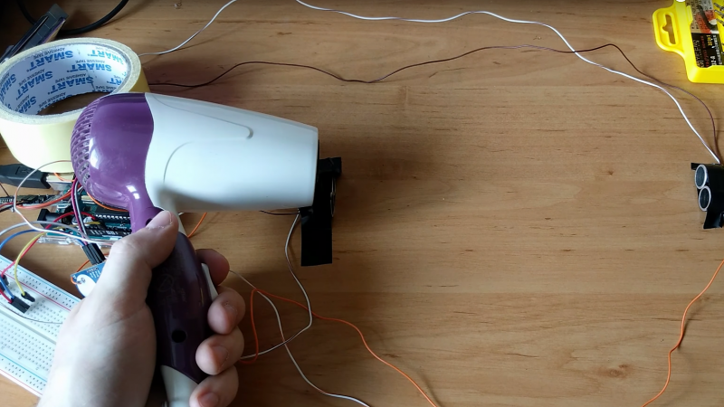
The principle behind the sensor [ItMightBeWorse] is working on is nothing new. He discovered a paper from 2015 that describes the method that measures the change in time-of-flight of an ultrasonic pulse across a moving stream of air in a duct. It’s another one of those “Why didn’t I think of that?” things that makes perfect sense in theory, but takes some engineering to turn into a functional sensor. [ItMightBeWorse] is using readily available HC-SR04 sensor boards and has already done a proof-of-concept build. He’s getting real numbers back and getting close to a sensor that will go into an HVAC automation project. The video below shows his progress to date and hints at a follow-up video with more results soon.
Here’s wishing [ItMightBeWorse] the best of luck with his build. But if things go sideways, he might look to our post-mortem of a failed magnetic flow meter for inspiration.
[via r/electronics]


How about as a replacement for the automotive MAF?
Nope. This only measures (a component of) a weighted average of some fraction of the airstream velocity. The whole point of the M(ass) in the Mass Airflow Sensor is that it measures the actual MASS of air entering the engine, independent of temperature and pressure, in order to get the air-fuel mixture (approximately) correct. The (oxygen sensors inputs are used to fine-tune it once they are warmed up and it can close the control loop).
Sure, you could add a pressure sensor and use the usually existing air temp sensor to predict air mass from velocity, but the MAF gives a single-sensor solution.
Thank the FSM MAF sensors have improved a lot over the years though. The old flappy-vane type were kind of miserable for accuracy and durability compared to the hot filament variety.
“Sure, you could add a pressure sensor and use the usually existing air temp sensor to predict air mass from velocity, but the MAF gives a single-sensor solution. ”
That’s actually what is done on heavily modified cars, because a MAF sensor won’t do good with a modified intake and it will have a lower resolution. The method that uses an air temp sensor and a Manifold Absolute Pressure (MAP) sensor is usually called “Speed Density”.
If you don’t have a calibrated instrument to compare to, you could strap it to the roof of a car and drive at various speeds on a calm day to generate known velocities for your own calibration.
TI also has a solution
Ti also has a solution, I forgo the link above http://www.ti.com/tool/tdc1000-tdc7200evm
See also: Ultrasonic Anemometers…
http://hackaday.com/2013/08/21/ultrasonic-anemometer-for-an-absurdly-accurate-weather-station/
(Sorry Dan, but it looks like that dastardly Brian got the drop on you :-)
Seems like I saw an ultrasonic wind speed and direction measuring device described in the ’70s, possible a Circuit Cellar or Amateur Scientist article, so the idea has been around a long time.
https://archive.org/stream/byte-magazine-1979-07-rescan/1979_07_BYTE_04-07_Automating_Eclipses#page/n121/mode/2up/search/dvorak
July 1979 Byte magazine, page 121, in case something goes wrong with the link.
a technique used in spirometry measurments is to mount the transmiter and receiver in line with each other and at an angle of about 15deg or so to the airflow so that the air flow “pushes” the US toward the receiver .
That ultrasonic sensor maybe does not introduce much resistance to the air flow, but maintenance issues are same or even higher: dust and debris would quickly coat the sensors, probably even faster than a good´ole flow meter, how is this method an improvement ?
Dust and debris would muffle the US somewhat, but that can be compensated. I assume that sensors would be sealed, like the ones on parking assistance.
We installed a Caldon ultrasonic flow meter in a nuclear plant a few years back. It was used to monitor the feedwater flow. The feedwater pipes are rather large (something in excess of 18″ IIRC) so the meter measured across 8 planes to get an accurate cross section and account for turbulence in the flow.
Pretty interesting technology. More accurate and less restrictive than the Venturi meter that used to be used.
Using doppler to measure air (gas) speed is nothing new.
However he is making a big mistake.
He is using a sensor with the transmitter and the receiver next to each other.
So the outgoing signal picks up a delay (Assume it is into the airstream).
And the bounced back signal rides along with the airstream.
And consumes most of the extra delay introduced by the moving air.
The solution is to separate the transmitter and receiver.
Put them on opposite sides of a pipe.
Not opposite ends. 1 transmitter on the side of the pipe, 2 receivers at other side. If the signal arrives at the same time, no air speed, as the speed increases, the difference increases, this reduces the effects of heat, air pressure variations and moisture on the speed measured.
Basically you are not swimming up stream, or down stream, but across the stream.
No, the point of using doppler is that it isn’t time of flight. You look at the beat frequency of the recombined signals from the transmitter and reciever to get the change in frequency to calculate doppler effect. Not the same as the method here, but it’s what paul is talking about.
If the sender and receiver are moving at the same speed, then the receiver measures the same frequency as was transmitted (in the steady-flow case).
Think about how many sound wave peaks there are between the sender and receiver: if there was a frequency difference, then that number would have to increase or decrease with time, and eventually there wouldn’t be any place to put the extra (or you would run out.)
In this case, what [ItMightBeWorse] is separating the transmitter and receiver. Module 1 has its transmitter and receiver desoldered and separated by about a foot. Module 2 has its transmitter next to module 1’s receiver and vice versa. If module 1 transmits downwind then it measures a shorter time-of-flight than module 2, and the difference in times-of-flight depends on the wind speed.
depends on wind speed and air pressure and air temperature and possibly humidity too.
Agreed, but this type of sensor needs a target from which to bounce its ping.
Placing the sensor and the target in direction of the airflow would interfere with it.
OTOH, if the sensor is placed so that sound travels perpendicular to the air flow, then the air flow is extending its round-trip path: the contact point of the incident wave front with opposite wall is moved downstream, and on the return leg it needs to travel upstream for even more time. Unfortunately though, it won’t discriminate between directions of the flow, only between different speeds.
I doubt this could be used in a weather station.
Some wx stations do use ultrasonic wind speed sensors, but this one wouldn’t last long in the wild.
have you proceed any further, Dan?
Hi
This is already a commercial product, released in 2017
http://www.lindab.com/global/pro/Pages/ultralink-next.aspx