
As ever, I am fighting a marginally winning battle against my 1991 Mazda MX-5, and this is the story of how I came to install a wideband oxygen sensor in my Japanese thoroughbred. It came about as part of my ongoing project to build myself a viable racecar, and to figure out why my 1990s Japanese economy car engine runs more like a late 1970s Malaise-era boat anchor.
I’ve always considered myself unlucky. My taste for early 90s metal has meant I’ve never known the loving embrace of OBD-2 diagnostics, and I’ve had to make to do with whatever hokey system was implemented by manufacturers who were just starting to produce reliable fuel injection systems.
This generally involves putting in a wire jumper somewhere, attaching an LED, and watching it flash out the trouble codes. My Mazda was no exception, and after putting up with a car that was running rich enough to leave soot all over the rear bumper, I had to run the diagnostic.
It turned up three codes – one for the cam angle sensor, and two for the oxygen sensor. Now, a cam angle sensor (CAS) fault will normally prevent the car running at all, so it’s safe to assume that was an intermittent fault to keep an eye on.
The oxygen sensor, however, was clearly in need of attention. Its job is to allow the engine control unit (ECU) to monitor the fuel mixture in the exhaust, and make sure it’s not too rich or too lean. As my car was very obviously running too rich, and the diagnostic codes indicated an oxygen sensor failure, a repair was in order.
I priced up replacement sensors, and a new oxygen sensor could be had for under $100. However, it wasn’t exactly what I wanted, as not all oxygen sensors are created equal. Cars in the 80s and 90s typically shipped from the OEM fitted with what’s called a narrowband oxygen sensor. These almost always consist of a zirconia dioxide cell that outputs a voltage depending on the difference in oxygen concentration between the exhaust gas and the free air. These sensors generally sit at 0.45 V when the fuel mixture is stoichiometric, but rapidly change to 0.1 V in a lean condition and 0.9 V in a rich condition. The response is highly non-linear, and changes greatly with respect to temperature, and thus is only good for telling the ECU if it’s rich or lean, but not by how much. ECUs with narrowband sensors tend to hunt a lot when running in closed loop O2 control – you’ll see an engine at idle hunt either side of the magical 14.7 stoichiometric air fuel ratio, never able to quite dial in on the correct number.
As I intend to switch to an aftermarket ECU in the future, I’ll need to tune the car. This involves making sure the air/fuel ratios (AFRs) are correct, and for that I need to be able to properly measure them. Just knowing whether you’re rich or lean isn’t enough, as often it’s desirable to run the engine intentionally rich or lean at certain engine loads. To get a true AFR reading requires fitting a wideband oxygen sensor. These are a little more complicated.
Wideband
Wideband sensors were first perfected in 1992 by NGK, and consist of a narrowband sensor combined with a special ion pump cell mounted in a small measurement cavity that has an orifice for exhaust gas to feed in. The wideband control module monitors the oxygen concentration in the measurement cavity through the narrowband sensor, and if it detects a rich condition, it controls the pump cell current to pump oxygen ions from the outside air into the cavity to consume the excess fuel molecules. In a lean condition, it reverses the pump cell current to evacuate excess oxygen ions from the measurement cavity. The wideband oxygen controller can determine the true air fuel ratio by monitoring the pump current required to keep the measurement cavity at a stoichiometric mixture.
As a wideband oxygen sensor system costs only around $250, it didn’t make sense for me to buy another narrowband sensor when I had to upgrade to a wideband later anyway. I chose the Innovate LC-2 wideband controller kit with the DB gauge. This comes with a Bosch 4.9 wideband O2 sensor, the LC-2 controller, all the cabling required to install & program the controller, as well as a nice green LED 52 mm gauge so you can regale your dates with your highly accurate knowledge of your car’s air fuel ratio. The LC-2 is a good controller for a setup like mine, as it includes an emulated narrowband signal output. This allows me to use the wideband controller with my stock ECU, while I save up for an aftermarket unit that can understand the wideband outputs.
The first step prior to install was to run a calibration on the wideband controller. To do this, the controller must be powered up with no sensor attached, and left for approximately 30 seconds until the LEDs flash correctly. Then, the controller must be powered down, and then powered back up with the sensor attached. I did this using a bench power supply, however the calibration failed as it could only deliver 1 amp which wasn’t enough for the sensor’s heater. A second attempt using an ATX power supply which could deliver more current was successful.
The main requirements of the install are switched twelve-volt power for the wideband controller. It’s important to find a power line that’s only on when the ignition is in the ON position. This is because the wideband sensor has a heater to keep it at the right temperature for measurement. If you run this directly off twelve volts from the battery, it will drain the battery even when the car is off, and also burn out the sensor. As my car is focused more on performance than creature comforts, I decided to commit to having no stereo in the car. If you insist on leaving your stereo installed, you may want to run a separate fused twelve-volt line instead.
With the stereo gone, I decided to install the gauge where the car stereo would normally go, and ran this off the same power lines, which was easy enough as a few LEDs only require a couple hundred milliamps at most. My father was kind enough to fab up a stereo blanking panel to fit the gauge into which looked incredibly tidy once installed.
Installation
The LC2 comes set up with two analog outputs, one wideband on the yellow line and the aforementioned emulated narrowband output on the brown line. I ran the wideband output directly to the gauge and ran the emulated narrowband output on a wire heading all the way back to the engine bay. It was easier to splice into the stock ECU’s oxygen sensor lines there, rather than fighting with a mess of wires under the glovebox. The trick was to cut a small slit in the main engine harness grommet on the firewall to pass my new O2 sensor line through.
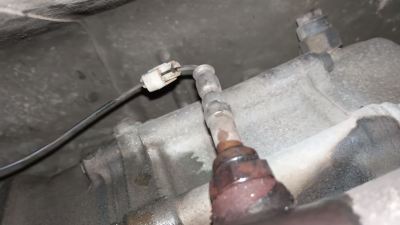
It was when I was running this wire that I realised the likely cause of the original O2 sensor failure. A previous owner had installed custom exhaust headers, which necessitated moving the original oxygen sensor to a new position. As the harness wasn’t the right size, they’d cut the original sensor’s line and spliced it together with a “quick-splice” connector. These things are universally awful and make terrible connections, and should never be used in an automotive environment, not even for a radio. This is almost certainly the reason the ECU wasn’t able to get a proper reading from the original oxygen sensor!
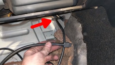
Next I had to figure out how to route the cable from the wideband controller inside the cabin to the sensor mounted in the exhaust. American Miata owners typically pass this through a spare grommet on the driver’s side of the firewall, however those of us that drive on the opposite side of the road don’t have this available. Working on an Australian-delivered car, I was instead able to find a grommet perfectly located on the passenger side footwell for a small air conditioning hose, and crammed my cable through there instead.
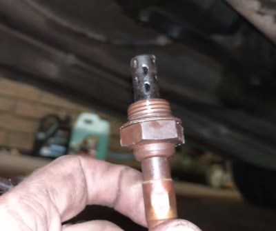
Unfortunately, the worst was yet to come. It was time to install the new sensor into the exhaust. The problem was the absolute butcher who installed the sensor previously. The sensor had been completely cross threaded and torqued to an ungodly level. After much soaking in penetrating oils, I was able to remove the old sensor, but the threads were now completely gacked, to use the technical term. There was no hope of properly installing the new sensor without first sorting them out.
Those who know me well will be aware that I don’t exactly work in the most well-stocked garages. The correct sized tap would allow me to quickly clean up the threads without much issue, but I own as many taps as I do double-decker buses. With the clock having struck midnight, there was absolutely zero hope of a trip down to the store either. Thankfully, this is where the junkyard expeditions of my youth came to save me.
In previous years, having tried to troubleshoot one of my former rides, I’d procured a couple of second-hand oxygen sensors from the junkyard. I was lucky enough to find one still lying around, and it was called up for duty. Very delicately, I inserted it into the sensor bung in the exhaust, getting it as straight and parallel as possible, before gingerly beginning to torque it down. Going a half-turn or so at a time, and then backing off a quarter, as is the technique, I managed to cut a serviceable thread back into the exhaust, and saved the day. The new Bosch 4.9 wideband sensor was thoughtfully already coated with anti-seize, and I was now able to gingerly thread it into place without further issue.
By this point, it was now 2AM and I was depending on this car to run so I could propel myself home to my nice, comfy bed. By some dumb stroke of luck, or perhaps because fundamentally getting this install right only depended on the correct soldering of six wires, it worked first time, and the gauge sprang into life reporting my engine’s AFRs! Once the engine was warm, one could plainly observe the ECU’s control loop hunting for a stoichiometric mixture either side of that magical 14.7 number. Success was sweet.
Overall, the install went remarkably smoothly for a project involving a 26-year-old car and some seriously stuck old parts. After several weeks of use I can report the sensor is functioning well, though my car’s fuel economy is still remarkably poor, meaning I must hunt further for other issues. I recommend anyone to take on this hack if you’re heading down a similar path of modification, and wish you all good luck with your own project cars. May they return to the streets before rust returns them to the earth of your back garden!


Turn it into an Exocet!!!
Be careful with those sensors, if your car is burning any oil it appears to knacker the sensors. My friend borrowed mine to tune his bike. Which transpired was burning oil. When I had it back months later. My bike showed a rich condition which I tried to tune out and promptly burnt my exhaust valves out
You can clean them by heating the tip cherry red with a blowlamp.
It’s certain sealants / instant gaskets people use on engines that give off acidic fumes that kill them dead. Loctite 598 is your friend.
This is a great way to finish killing the oxygen sensor….. Once they are gone they are gone. Wideband sensors tolerate even less. Also all modern sealants are sensor safe.
Silicone sealants in the exhaust stream damage the o2 sensor.
Surprisingly few car hacks on Hackaday, Nice one. The crank sensor fault can easily be verified with a timing gun, Either the bell housing or the block has timing marks and an opening to watch the mark on either the flywheel or crank pulley, check if the idle timing is steady and not jumping around. Then there is the obvious: vacuum leak (especially if this car was owned by a butcher before as you suggest) if you disconnect a vacuum hose at idle and nothing happens, you’re onto something, head gasket leak (bummer) oil film in coolant tank/creamy gunk on oil filler cap, worn rings (also bummer) compression test (cheap tool), dragging brakes, bad wheel alignment. When you finally get it sorted out, it will drive nicely, but getting to know a “new” old car is uphill the first 3 months. Take off the valve cover, it will show a lot about how the engine has been treated. Does it have an EGR valve? — it is clogged up 100% sure there.
Fun fact. Some cars have the timing mark on the timing belt cover instead of something solid like the engine.
I am heading down the same route (on a much older car) and appreciate hearing your woes and what you did to get this working.
Don’t entirely discount the cam angle sensor. On my car, a low oil pressure incident meant there wasn’t enough hydraulic pressure to keep the hydraulic cam chain tensioner solid, and the timing chain jumped two links. The car did still run, but it did not run well at all. If it had a CAS it would have been reporting an error.
I’m unstoppable: old oil residue on throttle body temperature sensor and mass flow meter, some substantial short in the electrical system putting a large load on the alternator.
Not read the article yet, but be aware that the innovate box needs periodic recal. I do mine every year, which seems good enough.
Read it now… I think that the thread for O2 sensors is the same as a standard sparkplug.
There are a few engines that used the M18 thread for their spark plugs, but most plugs are a bit smaller. I once built a bench with a set of spark plugs being test fired by drilling a piece of bar stock and hitting it with an O2 sensor tap, only to find it was a bit of a challenge finding the right spark plugs.
There are weld-on sockets available with or without a flange to cover even bigger holes.
For really big holes, hack the sensor mount out of a junkyard exhaust, gives you a nice big lump of steel to weld in. The skinny little weld-in bosses love to distort and make it hard to get the sensor in.
I know – I’ve CAD’d up one of those flanges at work. :)
I also replaced the oxygen sensors because the car was running too rich (which you can smell from the exhaust gases). In the end that wasn’t the fault; one of the spark coils was almost dying. I found out once it had shorted completely, with accompanying smoke coming out from underneath the motor cover.
I think you can easily check this; get another spark coil from the dump and put that in the motor, with spark plug, only so that the engine is airtight.
But leave the coil cable attached to the spark coil you’ve just taken out, connect a jumper cable between the spark plug body and ground, and check that the spark plug sparks when you run the engine.
I’m not a professional mechanic, so double check if that’s something you -definitely- shouldn’t do.
Or perhaps someone can come up with something easier (besides just replacing all the coils).
Once when my Suzuki Sidekick was running rich,
(An injector failed closed, and the ECU compensated by switching to “Limp Home” mode and making the A/F overly rich) I lit a cigarette lighter about a foot away from the exhaust pipe and a huge flame continued beyond the cigarette lighter! Kind of cool, kind of scary, kind of scorched my fingers.
Find a pinout for the coil and use an ohm meter to test the resistance of each coil inside the pack. Chilton’s used to give this kind of info, but I’m not so sure now days, might have to find a torrent with the mechanics/dealer manual.
Potted coils show spider- webs if it’s burnt. Jane solved a few of those over the years.
Meaning, if the coil is bad, spiders will attach webs to it?
Nah. Your friendly neighborhood Spiderman is a mechanic, and will note which ones are bad for you.
That Spider-Sense has other uses I see…
To make a quick & dirty tap, you take a dremel tool and cut a slot into the threads of the bolt (or whatever you’re using). This slot is needed to provide a cutting face on the threads and give the excess material somewhere to go.
This, but I tend to use a small (4.5 inch) angle grinder with a cutting disc in it. You can make a fairly serviceable tap like this but of course it wont be hardened but it will do for one or two jobs.
I did eventually buy a tap thread, but by then I was making bungs up on the lathe to weld into my own manifolds.
Never ran a innovate although they are the market leader, there’s plenty of other more diy projects out there for less money and more hacker friendly types. I used to use the JAWS although I switched to the SLC more recently, and I see now theyve open sourced the code and for $35 + wire and a suitable sensor much nearer my expectations + I can fit them inside my megasquirt case keeping it all in one enclosure. Search for slc-free anyone is curious.
I had a car running rich because the coolant temp sensor had gone bad and was indicating “always cold”. The ECU was programmed to make the mixture rich for a cold engine – never went into closed loop mode. Also pre-OBD-II. Very sooty exhaust system and mileage was poor, but it ran fine with the rich mixture.
Please crop the graphics, it’s boring enough to have long articles about cars, but do you really have to import the sexism from the car community?
Do you really have to import the boredome with cars from the people-bored-with-cars community?
I’ve never understood the fascination with posting pictures of lightly clad women/men when discussin unrelated subjects, a tradition which is rampant in the car community. Your comments just prove my point.
Oh I agree with you actually Erik. I’m just confused that you’re complaining that cars are boring on a thread about cars.
How genderist of you.
Graphics are sexist?! More car hacks please!
I’m commenting too much on this article, but I think the graphics is a reference to the A-HA music video “Take on me”
I didn’t think of it that way.
I wonder if Mr. Kim will clarify for us?
But if he did, the crybabies will probably tear into him….
P.S. thanks for your earlier comments!
Never fear! The SJW is here! All jokes aside… Your lack of understanding is also irrelevant to the topic at hand. Have a great day.
That is like being displeased with a ring girl at a boxing match… It just goes with the territory.
And if this female has an issues with being objectified, she can just complain, O wait, she cant, she is a drawing.
I’m about to replace my SAAB 900’s stock O2 sensor and replace it with a Bosch 4.9 wideband. Thankfully my AEM Uego does have the ability to emulate a narrowband signal if you change the position on the ‘calibration’ switch to position 4. Unfortunately I have to keep the stock O2 sensor connected (and floating around in the engine bay) so I don’t get an OBD code for an open circuit heater… Instant emissions fail in New York.
I lied, just hooking up the wideband controller to the +12V for the stock O2 sensor heater. No need to leave the stock O2 sensor hanging around. :)
Somebody put headers on a Miata? Talk about a waste of time and money.
Not true – some gain to be had, particularly if doing a serious NA build.
Your fuel economy issues might be partially due to switching to (relatively) gigantic wheels vs the stock 14″ deals, especially if you’ve gone wider than the stock 175 or 185 profile tires. Unsprung weight and moment of inertia is a bitch.