As ever, I am fighting a marginally winning battle against my 1991 Mazda MX-5, and this is the story of how I came to install a wideband oxygen sensor in my Japanese thoroughbred. It came about as part of my ongoing project to build myself a viable racecar, and to figure out why my 1990s Japanese economy car engine runs more like a late 1970s Malaise-era boat anchor.
I’ve always considered myself unlucky. My taste for early 90s metal has meant I’ve never known the loving embrace of OBD-2 diagnostics, and I’ve had to make to do with whatever hokey system was implemented by manufacturers who were just starting to produce reliable fuel injection systems.

This generally involves putting in a wire jumper somewhere, attaching an LED, and watching it flash out the trouble codes. My Mazda was no exception, and after putting up with a car that was running rich enough to leave soot all over the rear bumper, I had to run the diagnostic.
It turned up three codes – one for the cam angle sensor, and two for the oxygen sensor. Now, a cam angle sensor (CAS) fault will normally prevent the car running at all, so it’s safe to assume that was an intermittent fault to keep an eye on.
The oxygen sensor, however, was clearly in need of attention. Its job is to allow the engine control unit (ECU) to monitor the fuel mixture in the exhaust, and make sure it’s not too rich or too lean. As my car was very obviously running too rich, and the diagnostic codes indicated an oxygen sensor failure, a repair was in order.
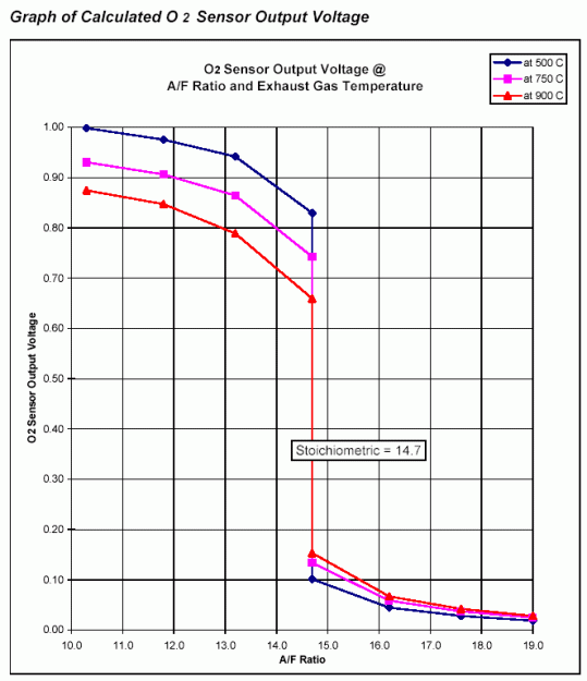
I priced up replacement sensors, and a new oxygen sensor could be had for under $100. However, it wasn’t exactly what I wanted, as not all oxygen sensors are created equal. Cars in the 80s and 90s typically shipped from the OEM fitted with what’s called a narrowband oxygen sensor. These almost always consist of a zirconia dioxide cell that outputs a voltage depending on the difference in oxygen concentration between the exhaust gas and the free air. These sensors generally sit at 0.45 V when the fuel mixture is stoichiometric, but rapidly change to 0.1 V in a lean condition and 0.9 V in a rich condition. The response is highly non-linear, and changes greatly with respect to temperature, and thus is only good for telling the ECU if it’s rich or lean, but not by how much. ECUs with narrowband sensors tend to hunt a lot when running in closed loop O2 control – you’ll see an engine at idle hunt either side of the magical 14.7 stoichiometric air fuel ratio, never able to quite dial in on the correct number.
As I intend to switch to an aftermarket ECU in the future, I’ll need to tune the car. This involves making sure the air/fuel ratios (AFRs) are correct, and for that I need to be able to properly measure them. Just knowing whether you’re rich or lean isn’t enough, as often it’s desirable to run the engine intentionally rich or lean at certain engine loads. To get a true AFR reading requires fitting a wideband oxygen sensor. These are a little more complicated.


