It used to be that designing hardware required schematics and designing software required code. Sure, a lot of people could jump back and forth, but it was clearly a different discipline. Today, a lot of substantial digital design occurs using a hardware description language (HDL) like Verilog or VHDL. These look like software, but as we’ve pointed out many times, it isn’t really the same. [Zipcpu] has a really clear blog post that explains how it is different and why.
[Zipcpu] notes something we’ve seen all too often on the web. Some neophytes will write sequential code using Verilog or VHDL as if it was a conventional programming language. Code like that may even simulate. However, the resulting hardware will — at best — be very inefficient and at worst will not even work.
We did mildly disagree with one statement in the post: “…no digital logic design can work without a clock.” However, [Zipcpu] goes on to elaborate and we agree with the elaboration. However, it is important to note that asynchronous and combinatorial logic don’t use a clock in the conventional sense of the word. Combinatorial logic — for example, a bunch of AND and OR gates — can only handle simple tasks and full-blown asynchronous design is tough and not likely to be something a new FPGA developer will encounter.
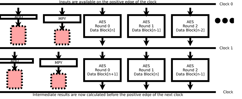
The reality is that nearly all significant digital design uses clocks is because it makes the design manageable. Essentially, the clock tells all parts of the circuit to start processing and sets a deadline for the various combinatorial parts to complete. Without the clock, you’d have to deal with the issue when, for example, an adder presents a result before the carry from another stage arrives to change that answer. With a clock, as long as the right answer is ready by the clock edge, you don’t care about exactly how long it takes.
This is especially important because Verilog and VHDL don’t execute line-by-line as a software developer would expect. Instead, HDL constructs become circuits and all the circuits operate at one time. This parallelism can be difficult to manage, but it is what makes FPGAs ideal for high-speed computations and fast response times.
The section of the post about how much logic to put between clocks is what you usually call “making timing.” The FPGA tools have a scary amount of data about how much time it takes for a signal to travel from one part of the FPGA to another. If the tool detects that the transit time between two clocked elements exceeds the clock period, it will flag that as an error. You can increase the clock speed or shorten the path either physically or logically.
Overall, this is an excellent introduction to a tough subject and has a lot of real-world advice in it. If you want to read our take on it, we did a multipart Verilog tutorial using the inexpensive Lattice iCEstick board. There’s also a practical example using the same board. The tutorial even had some videos, the first of which appears below.


“The section of the post about how much logic to put between clocks is what you usually call “making timing.” The FPGA tools have a scary amount of data about how much time it takes for a signal to travel from one part of the FPGA to another.”
Better too much than too little.
To paraphrase John Archibald Wheeler, clocks are a logic designer’s way to keep everything from happening all at once.
I studied Electronic Systems Engineering in university, and really enjoyed the classes involving FPGA circuit design. Since graduating, I’ve never used those skills – not at work, nor in personal projects. I have a Virtex-II that I found in a recycling bin, but I still don’t have a practical use for it.
My impression is that the only people designing circuits these days are working for large companies in the US (Intel) or UK (ARM, Broadcom). The designs are sent to Taiwan for manufacturing, which is where I’m working now. But my work involves control systems software for testing machines, instead of any local designs. All the resources are here to build something exciting, but I haven’t got any projects that would require it.
Even for my Virtex-II, what should I use it for? It seems that everything can be done in software, and pocket-sized single board computers can meet the needs of all my personal project ideas.
I’d like to know what other people are using their FPGAs for, so I can be inspired to build something unique and useful.
Build a device that takes the Rigol DS1052E parallel video signal on the motherboard (there is a convenient connector already on the motherboard) and convert it to DVI or HDMI.
Then put that on Ebay, and I’ll be one of your first customers.
FPGA people may say it’s trivial, but not for beginners!
RoGeorge did it in software for the DS1000Z. His solution uses SCPI commands, which should also work on the DS1052E.
https://hackaday.io/project/5807-driverless-rigol-ds1054z-screen-capture-over-lan
Everything arround fast signal processing is usualy done by an FPGA (or an ASIC).
I used to work on NFC certification tools for several years, and given the response time needed (µs scale) and the algorithms involved, the only solution was that.
Same for handling highspeed communication as ethernet.
While the likes of ARM are one of the few big companies in the synthesisable design world (i.e. HDL code that can be ‘compiled’ into different digital logic be that FPGA or ASIC), there are hundreds more that either buy that code (and so have to write more to integrate it into a complete/finished system) or simply write their own for specialist applications.
You just have to look at the companies that buy ARM IP (things like the CPU cores) to see what other businesses use HDL experts – Broadcom are one such company. Outside of the CPU world, there are a lot of other companies that employ FPGAs as a means to process large quantities of data in application specific manners (think video processing, networking, defence industries, etc).
And as for projects to use your Virtex-II board in, forget trying to implement CPUs in them as it’s not worth the effort, instead think of hard-real-time critical things (possible in software but can require obsessive care with how the code is compiled) and massively parallel tasks (they don’t have to be complex, just sufficiently many of them that, unless you have a GPU to throw the job to, it results in a delay as the task become serialised).
I have worked at large semiconductor houses (in the US), and did a lot of digital design on mixed analog/digital projects.
A lot of analog chips use small to medium amounts of digital logic for internal things like storing calibration/configuration data. Anything that has an I2C or SPI interface will have digital logic. Not all of this is done in Verilog/VHDL though. The analog design people tend to instantiate the digital logic manually, while projects with digital design people and larger amounts of digital logic sections will be done with Verilog/VHDL.
I have also done a lot of FPGA work implementing specialized digital interfaces for testing new chips. It may be a standard digital interface protocol with configurable timing or it may be non-standard interfaces that are not published.
Personally, I have done a few FPGA home projects to create peripherals for microprocessors that are not commercially available. I will probably be doing another one for adapting LCD types to repair equipment with failed displays that are unavailable now.
I currently work (rather slowly) on a project using an FPGA to take high-speed ADC information and send it (together with some additional project information e.g. scaling factor) to a PC where I plan to have an interface which can work as oscilloscope, spectrum analyzer, logic analyzer, etc using the information received. A simple project but it’s a nice start. It will have you creating a sort of communication protocol, dealing with constant streams of data from the ADCs, etc.
Another project you could try, since you’re into control engineering is creating various regulators in the FPGA and control various devices with it. I did this for my Masters’ Degree, doing a comparison between 4 different advanced regulator designs and the plain old VMC of a buck regulator. It was a nice project which taught me a lot (it was my first real project with an FPGA).
Hope this helps with inspiration…
You need to select a project that is well suited for FPGA implementation. Your Virtex-II is quite dated, so many things that it would be suitable for can now be done by a CPU or GPU, but for learning this should not matter.
Some examples:
– Software defined radio PHY implementation.
– Everything related to video processing
– Bruteforcing hashes etc
– Protocol conversion
CPUs are moving in the direction of combining with blocks of FPGA fabric to allow custom high speed functions. The latest Intel Xeons are an example of this.
Meanwhile FPGAs are moving towards having more complex fixed IP on board that can be hooked together with the standard fabric to handle particularly fast or complex tasks. High speed (multi-gigahertz) tranceivers or, in the latest chips, complete ARM CPU cores are examples.
Both CPU and FPGA have their strengths and weaknesses. Many projects that need the speed and/or timing accuracy of FPGAs don’t have the production volume needed to convert them to full ASICs. There’s also no ability to make changes to an ASIC design (short of ripping it out and replacing it) that can be an issue for some envionments.
To cut a long story short, you might not yet have encountered something that you want to do that a CPU can’t handle, but the design world can see the writing on the cards and is heading towards giving you both together.
bitcoin mining open source
what car do you drive?
modern cars (certainly Japanese ones) are now being fitted with gvif for the video and it’s maddening. i need to put an aftermarket stereo in mine but i don’t want to lose the factory cameras.
you’d need an fpga or cpld to decode the Gigabit video interface and turn it into (horrible) old CVBS
“If the tool detects that the transit time between two clocked elements exceeds the clock period, it will flag that as an error. You can increase the clock speed or shorten the path either physically or logically.”
Should that say DECREASE the clock speed — i.e. lengthen the clock period?
Oops. I was thinking “increase the speed grade of the device” and I just blew it. Some FPGAs come in speed grades that have lower propagation times than slower devices. You are right, though, you can also decide to slow down if that’s an option (no offense to Reverend Jim).
Bah… clock your programmable logic fabric at 10X your I/O requirement and hope for the best.
Quote [ Al Williams]: “Some neophytes will write sequential code using Verilog or VHDL as if it was a conventional programming language.”
Although the linked article loosely refers to a HDL the information in the article clearly relates to Verilog.
Verilog contains both ambiguity and a confusing syntax. In Verilog you can actually write code that has an ambiguous logical meaning and it may or may not synthesize. System Verilog is the solution to this problem.
Verilog also has the problem (confusion) that it looks like a programming language and some people confuse compiler directives with synthesis. For example For-Next, a coder may think that they are writing a loop that will run in the hardware but instead they are directing the compiler to make x blocks of the hardware contained in the loop,
These things are not possible with VHDL. There is no capacity to write anything that has an ambiguous logical meaning as the compiler won’t accept it.
Nice read all same. I hope I got these points right as I code in VHDL and not Verilog.
“There is always a clock”
This may have been one of the most mis-understood comments in the article I wrote. At one time while drafting the article I had a paragraph that I had used to try to explain that comment, but then took it out for whatever reason before posting the article. To date, those who have “disagreed” with me have yet to disagree with the meaning behind the statement.
One reader provided an example of a parity circuit (VHDL module) with no clock input to the module. This was his counter example to “prove” that circuits could be made without clocks. Had he instead zoomed out from his parity module to the rest of his design, he would’ve found the clock within his design.
The clock doesn’t need to be within the FPGA, and it doesn’t need to be managed, but it will be present. Hence, even though asynchronous design does have a clock “in the conventional sense”, there is still a clock.
As an example, I once had the opportunity to build a traffic cop within an FPGA that needed to arbitrate from several sources that might access and read/write an SD-Card. The FPGA logic was “asynchronous”, so you might argue there was no clock in the design. I would disagree: each of the external sources that wished to access the SD card had a clock. Despite this being an “asynchronous” design, therefore, there was still a clock.
This may not have been a clock “in the conventional sense”, but there was still a clock.
The only place where the statement starts to fall apart that I’ve seen so far is in user interaction. Interacting with computers or other external electronic circuitry will require logic that matches the clock of this external circuitry, but human users are a different. Users can press buttons and see LED outputs, and in such cases there is arguably no clock. In those examples, though, there is still a time when the initial data and conditions became valid, and another time later when the outputs became valid. Between those two times, the logic output of the FPGA is uncontrolled and may do anything. In and of itself, this situation creates features much like a clock might, but without having a regular time interval defining when inputs are valid and outputs must be valid.
So, in spite of the arguments I have read to the contrary, I will still maintain the statement: “There is always a clock.”