If you turn over almost any electronic device, you should find all those compliance logos: CE, FCC, UL, TÜV, and friends. They mean that the device meets required standards set by a particular region or testing organisation, and is safe for you, the consumer.
Among those standards are those concerning EMC, or ElectroMagnetic Compatibility. These ensure that the device neither emits RF radiation such that it might interfere with anything in its surroundings, nor is it unusually susceptible to radiation from those surroundings. Achieving a pass in those tests is something of a black art, and it’s one that [Pero] has detailed his exposure to in the process of seeing a large 3-phase power supply through them. It’s a lengthy, and fascinating post.
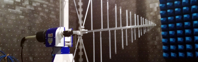
He takes us through a basic though slightly redacted look at the device itself, before describing the testing process, and the EMC lab. These are fascinating places with expert staff who can really help, though they are extremely expensive to book time in. Since the test involves a mains power supply he describes the Line Impedance Stabilisation Network, or LISN, whose job is to safely filter away the RF component on the mains cable, and present a uniform impedance to the device.
In the end his device failed its test, and he was only able to achieve a pass with a bit of that black magic involving the RF compliance engineer’s secret weapons: copper tape and ferrite rings. [Pero] and his colleagues are going to have to redesign their shielding.
We’ve covered our visits to the EMC test lab here before.


The ferrite ring of shame.
Usually failures are the result of ignoring good design practice, and even attentiveness won’t guarantee anything.
Some chip that is supposed to have a heat sink can splatter across the spectrum even if well within thermal ratings.
DRAM, video cores, and Ethernet transceivers are famous for hard to locate harmonic noise given they have nothing to do with the PCB itself.
However, passing FCC and CE testing is fairly easy if you routed the HF stuff by hand first, and follow EMI mitigation guidelines from the start.
Some labs are dubious, so make sure you scan you own device before and after it is tested. Although your equipment may be inaccurate, this will ensure when you must modify the design to lower the emissions by X amount as required, that the lab-assistant can only screw your team once with additional bills (cost us about $20k to learn this audit process).
You can sometimes rent EMC chambers of universities quite cheaply. Think around 500€ for a day. They are of course not certified, but usually the results are within 1-2dB of a ‘real’ lab.
Most labs will do the pre-scan for about the same price, but you will need a way to know if you are getting ripped off by their engineers.
I highly recommend people attend the testing to ensure the lab workers actually do the tests correctly, and to ask questions you already know the answer to in addition to what you actually want to know.
I usually ask students to use a $10 RTL SDR dongle at home to avoid congesting the lab schedules:
1. Get xtal ppm correction from cell tower:
https://github.com/steve-m/kalibrate-rtl
2. Off/On spectrum comparison after calibration (@24dB LNA gain) is usually within 5dB of the lab, but you are actually more interested in the relative change in emissions (at the exact test positions) after the failure is disclosed given it should correct your own initial uncalibrated reading (testing closer at something like 20cm on every side will show the peak-noise level clearly… if it failed FCC):
https://github.com/EarToEarOak/RTLSDR-Scanner
3. Don’t disclose you have already profiled the emissions until after the device is scanned again on your bench for comparison after returning from the lab. You will need the lab data to detect where the problem is coming from, and if you actually fix the issue.
Keep in mind that other classes of EM testing are far stricter, and will require the professional equipment in a chamber to lower the noise floor. The FCC rules are relatively easy to get right, but you need to be aware how some of these lab guys operate. The meetings get awkward when you catch companies intentionally/unintentionally lying to your team. Also, make sure all report copies are emailed… so you can correct the invoice if they do something stupid, and you can prove it.
Many thanks for sharing the kalibrate-rtl project, it’s a original way to calibrate a RTL-SDR. Unfortunately the http://thre.at/kalibrate link don’t actually work so I am a bit lost at the stage of interpreting the following results:
Found 1 device(s):
0: Generic RTL2832U OEM
Using device 0: Generic RTL2832U OEM
Found Rafael Micro R820T tuner
Exact sample rate is: 270833.002142 Hz
chan: 49 (944.8MHz – 97Hz) power: 138931.37
– 106Hz [-128, -86] (41, 10.090870) 0.113 ppm
– 103Hz [-128, -75] (53, 13.655234) 0.109 ppm
– 105Hz [-131, -80] (51, 12.793691) 0.111 ppm
chan: 102 (955.4MHz + 294Hz) power: 40671.79
+ 270Hz [198, 338] (141, 34.281021) -0.283 ppm
+ 246Hz [145, 328] (183, 40.866386) -0.258 ppm
+ 265Hz [213, 344] (131, 33.819973) -0.277 ppm
chan: 113 (957.6MHz + 381Hz) power: 45720.19
+ 368Hz [338, 394] (56, 16.174734) -0.384 ppm
+ 370Hz [349, 392] (43, 11.892882) -0.386 ppm
+ 366Hz [340, 388] (48, 14.981081) -0.382 ppm
chan: 971 (924.4MHz + 987Hz) power: 30016.48
+ 986Hz [898, 1053] (155, 41.783783) -1.066 ppm
+ 991Hz [912, 1069] (157, 43.861740) -1.072 ppm
+ 990Hz [921, 1067] (146, 36.333637) -1.071 ppm
What conclusion can be made about this particular RTL-SDR ?
@jcamdr
#warm up SDR by listening to gqrx fm radio for 15 minutes
#find strongest/closest GSM tower channel number without AGC
kal -s GSM850 -b GSM850 -g 42 -e 0
#find absolute error PPM to correct your apps (example use of channel number 49)
kal -c 49 -b GSM850 -g 42 -e 0
#Follow application specific device gain and ppm error profile configuration
#Note most RTL use a 70 ohm input: so only an antenna input is recommended, and your conversion math may need a bit of tweaking.
#Your data should be repeatable within a few kHz… I tend to only link git hub pages from the authors sites given not everyone remembers to update blogs.
Using the RTL SDR as a pre-scan sounds like a brilliant idea. For a quick scan in your own lab, what would your test setup look like? I.e. which kind of probes/antennas would you use, how would you position them and how would you connect them to the dongle?
I once had the task of meeting a standard significantly more strict than FCC with an old product that had not been designed with EMI in mind. Yeah, I used a lot of ferrites.
I’m not proud of the result, but it kept us in business until we could design a new product that passed without all the add-ons.
Over the years, you get experienced enough to avoid most pitfalls during the design phase, mostly without even thinking about it.
And you learn how to use standard simulation tools to also solve EMC issues.
Maybe an explanation of why it’s so much of a black art?
Tip for the author: spread spectrum clock generator. If you modulate the clock then it will spread over a larger part of the spectrum, bringing the signal density down. Assuming the system manage with a clock whose frequency moves around a bit around some average value..
The best way to prepare yourself and your hardware for your first few compliance tests is to actually leave space in your design for additonal filtering. Make room for some capacitors at the IO connectors, put some zero-ohm resistors into the signal paths so you can exchange them for ferrite beads, add footprints for capacitors on sensitive signals (resets getting triggered by ESD is one common pitfall)…
Of course, if your power output designed for a few amps of current needs a hefty common mode filter to pass, you’ll probably have to redesign that board, but making room for a few smd components at the right places can sometimes save you a board redesign and allows you to modify and improve your design “on the spot” (in the EMC lab) and get successful reports quicker and cheaper.
Ohhhh, that’s why there’s numerous, seemingly pointless zero ohm resistors all over revision 1 of a board.
Hardware has something in common with software; shipping the prototype. ;-)
Followed by “Wow, shit, ppl will actually buy this piece, well then, better cost reduce it and shine it up..”
It’s a monster piece :-)
Look out for copper tape – it can give you wicked paper cuts.
Totally agree with Magpie about leaving space for some filter Rs and Cs.
Lookout: they keep changing the specs. I did my first EMC test in the mid-90s and the upper frequency limit of that scan was something like 1GHz.
My last major product (a year or two ago) was scanned up to Ka band.
It had a failure by a few dB at 25GHz(-ish), due to radiation from an air vent that had been fashioned from small slots in the case. The slots were only about 15mm long.
This was fixed by a thin piece of copper tape at the lab and a later design change to break each slot into three shorter slots.
Back the ’90s I never would have dreamed that a slot that small would be a problem for a “digital” board.
Way to halfass it, now it’s gonna have a problem at 75Ghz :-D
It isn’t black magic, it’s electromagnetism and it is actually quite well understood. I don’t mean to sound smug or anything as I was a bit nervous myself when I entered a lab the first time. Just relax, if you are smart enough to get there in the first place I am pretty shure you are smart enough to use common sense and good old fault finding to sort things out. Some homemade probes, current clamps and an oscilloscope will go a long way as sanity checking before you go to the lab.
Difference between art and science is repeatability. Do this specific thing and that specific response shows up. Do that specific thing and it doesn’t show up till you wiggle it is art.
Reality has heisenbugs.
Hell yah, those really screw with your brain. Like when you are fairly sure you got something right but there’s room for doubt, and it doesn’t work…. then you go through everything from first principles, convince yourself 110% you’ve done nothing wrong… and it starts working.
Drives me absolutely crazy when the management at the WISP I work at say that RF is “voodoo.” It’s really not. You just have to listen to the guy that is telling you that ‘the thing you want to try’ isn’t going to work.
I’ve done some testing at CKC and it was fascinating. Some of the restricted 5ghz spectrum is hard to avoid interfering with.
I’ve gone down the EMC path once before. Read the good books from Ott and others. I get In Compliance magazine! I know what to do, what not to do. Keep inductance low. Slots in the ground plane, blah blah, we all know it. Literally spent 6 months trying to quiet a SMPS switching at 1 MHz to pass DO-160G conducted emissions. (28V to 5V @ 8A!!!)
I went through app notes, and guides, hints, tips, tricks, component placement, copper tape, shield here, shield there. Filters, CM chokes. Finally found a configuration that worked, which involved grounding a shield to VERY specific points and with a very specific geometry and orientation. I know its NOT voodoo and magic, but damn if I wont jokingly call it black magic and voodoo for the rest of my life. Calling it voodoo and black magic is like the inside joke to those who have been trapped in the EMC chamber for months on end. ;)
On my last project I discovered that power supplies which claim to be EMI compliant…aren’t
Tried a bunch of power supplies. None would pass conducted emissions. We finally threw in a line filter.
Sometimes EMI is black magic… and sometimes it is more magic.
LOL. That was a great story!
The issue is the lack of excellent simulation tools. All of this can be modeled if your pockets are deep enough.
The US Milspecs for EMI/EMC (MIL-STD-461 and -464) give a surprisingly approachable pile of information about setting up and performing compliance tests on your own. Granted, the actual limits differ from e.g. FCC part 15, but the doc starts by showing how to build your own LISN, and from there the details of setting up the benchtop, antenna construction and placement, how to make a reasonable impulse generator from a well-charged capacitor and a length of coax, etc. If nothing else, it’s a good reference for your own pre-testing before dropping the bucks on the certified lab.
This is all talking about doing things properly and by the book, which engineers in most western countries do.
Most engineers (sorry, management of the engineers) in eastern countries just pay the label printing company (down the road) to print whatever they want the compliance sticker to say!