In the real world, components don’t work like we imagine they do. Wires have resistance, resistors have inductance, and capacitors have resistance. However, some designers like to take advantage of those imperfections, something our old friend [Ken Shirriff] noted when he was restoring the CRT of a Xerox Alto.
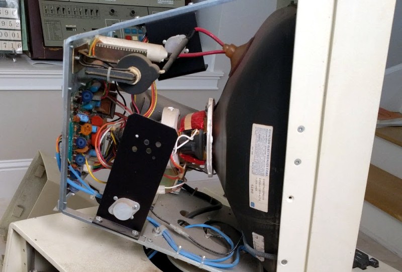
[Ken] tried to connect a Xerox monitor to the Alto and — since it was almost as old as the Alto — he wasn’t surprised that it didn’t work. What did surprise him, though, is that when he turned the monitor off, a perfect picture appeared for just a split second as the unit powered off. What could that mean?
Keep in mind this is a CRT device. So a perfect picture means you have vertical and horizontal sweep all at the right frequency. It also means you have high voltage and drive on the electron guns. If you are too young to remember all that, [Ken] covers the details in his post.
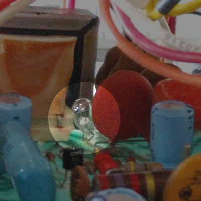
He found that the CRT grid voltage wasn’t present during operation. The voltage derived from the high voltage supply but, mysteriously, the high voltage was fine. There was a small lightbulb in the grid voltage circuit. A 28V device about like a flashlight bulb. It measured open and that turned out to be due to a broken lead. Repairing the broken lead to the bulb put the monitor back in operation.
 On paper, a light bulb lights up when you put current through it. In real life, it is a bit more complicated. An incandescent filament starts off as almost a dead short and draws a lot of current for a very brief time. As the current flows, the filament gets hot and the resistance goes up. That reduces the current draw. This effect — known as inrush current — is the scourge of designers trying to turn on light bulbs with transistors or other electronic switches.
However, the unknown Xerox power supply designer used that effect as a current limiter. The short 600V pulses would hardly notice the light bulb but if too much current or time elapsed, the resistance of the bulb would rise preventing too much current from flowing for too long. With the bulb open, the negative brightness grid provided an impassible barrier to the electrons. Apparently, the brightness grid lost power a bit earlier than the rest of the circuit and with it out of the way — or perhaps, partially out of the way — the picture was fine until the rest of the circuit also lost power.
We looked at [Ken’s] efforts on this machine earlier this year. Light bulbs, by the way, aren’t the only thing that changes resistance in response to some stimulus. You might enjoy the 1972 commercial from Xerox touting the Alto’s ability to do advanced tasks like e-mail and printing.


You have a very obvious typo in your title, sir.
Maybe that’ll be the name of my band, “Saved by Xero”.
Shouldn’t it be “CRT’s” instead of “CRTs”?
– If it would be the first case, written with “CRT’s”, I would understand the title as “This unit needed a lightbulb to be able to work again”.
– In the second case, written “CRTs”, I would understand the title as “Back in the days, the Alto model was needed a lightbulb (by designed) in order to work.
I am not a native speaker of English, so I’m not sure how it should be.
Can anybody clarify this to me, please?
CRTs is correct. Plural of CRT: “Cathode Ray Tubes”
CRT’s would be possessive, example: “The CRT’s grid voltage…”
Either one is perfectly acceptable actually. There is no formal, set in stone, rule for this.
That’s a finer point of english punctuation that is probably OK either way and is more of stylistic choice. (Reference: https://owl.english.purdue.edu/owl/resource/621/01 TLDR; apostrophe usually not needed after numbers/symbols/capitalized acronyms.)
Both your readings of the title are correct, though, and I’d argue that the second is the primary point.
Much clear now, thank you all.
Also, for those who don’t know, incandescent bulbs stabilize on passing enough current to dissipate about whatever power they’re rated for, almost irrespective of voltage. If you need a power limiter for some very primitive AC hack some bulbs in series with your load work pretty well.
They are often used for tweeter protection in speaker crossovers.
I have seen that in some BOSE speakers. I was testing them and was confused why light was coming out of the speaker. I took it apart and found several small light bulbs.
I used to have a panel with three series mains voltage bulbs that were in series with a mains socket. I was used when repairing TV’s like a poor mans variac.
If a TV have a load short then the bulbs would light up instead of parts exploding.
Quadcopter people use 12v automotive tail light bulbs for this same purpose, if there’s a short the short can almost always survive more current than the bulb will allow, and if there’s no short the electronics will all run happily without drawing enough to light the bulb.
The motors are another story.
Back in the ’70s and ’80s, I kept several incandescent bulbs of different wattages, all with cords and alligator clips. They’d get clipped to the terminals of fuse holders when a TV or other device was blowing fuses. You could often find the problem that way without blowing anything up. I also sometimes used a variac with an ammeter in the output for similar reasons, turn it up until the current goes as high as you want. If all goes well, take it all the way up to line voltage. Often loads were non-linear to the point that the variac was hard to control, bulbs worked better in that case.
No, they stabilize the current to a somewhat constant value, slightly falling with voltage. So the power is definitely not constant. They do not exhibit negative resistance.
Not as fancy use case but I recall Realistic Mach One speakers used a lightbulb to manage current limiting voice coil damage.
Dittto the Optimus T120’s.
I loved the Mach One’s. for the price they were good speakers.
Aren’t PTC (reset-able) fuses used for this sort of effect in modern applications? Like, a loudspeaker or siren or spotlight. You put one in parallel with the load, and if it draws too much current for too long, the fuse heats up and becomes a fat resistor that soaks up the extra current or something like that?
I think I read that on wikipedia somewhere.
I love this article and could really get used to more of these. One of my favorite 1970’s electronics books had a article every week from a repair man about his star repair of the month, loved them to.
This is a really interesting tube. I have seen pic of the monitor but never inside the monitor before.
I just assumed that it was a normal tube that was sideways but it a complete custom build.
The anode cap is 90 degrees from where you would expect it to be on a normal tube and the aspect ratio looks different to.
There is also one very noticeable difference when you look at the schematic.
The tube has an extra grid for retrace blanking and that is where this bulb is. It’s being used for it’s positive temperature coefficient and a suitably low vale solid state PTC would make a good replacement.
It has a second purpose in this design that is needed because of the extra grid.
A tube is like a big capacitor that stores thousands of volts so when the PSU is switched off there is still a very high voltage in the tube. With the PSU off there is no deflection so all that stored voltage in the tube would result in a very bright spot in the middle of the screen that would eventually burn the phosphor.
To solve this problem TV’s had a circuit that was called a spot killer but this is different as it has an extra grid that is only for retrace blanking and the spot killer.
Quite a few monochrome tubes had the anode cap on the short side rather than the long side of the tube where it typically is on more modern CRTs. I don’t think there was anything particularly special about this CRT, it looks like a normal 4:3 B&W CRT to me. Vertical monitors always look taller than a normal horizontal monitor is high, it’s a trick of the eye.
In a similar vein, older Bosch charging circuits depended on a light bulb to provide the starting current for the generator/alternator. I learned this when I had a VW that would sometimes charge fine, other times there was no excitation for the rotor. I had been ignoring the burnt out bulb, after all, what could that matter? My BMW motorcycle uses the same basic circuit. I’ve put a resistor in parallel with the bulb in every such vehicle I’ve owned since that VW Rabbit to avoid getting stranded due to a burnt out light bulb.
Here’s the circuit for those who are curious, I put it up on my site back in the early ’90s (and wrote an article the BMW Owners News)
http://www.buchanan1.net/charge.html
Since this started with computers from the ’70s, that schematic was drawn on a CAD system running on a Data General S280 Eclipse. Washing machine sized disk drives and all.
“newer” VW’s from late 80’s to late 90`s used a power resistor to “start” the alternator, but a LED with its own lower wattage resistor, in parallel with that big boy resistor as the dashboard charging indicator.
Using a small bulb for both indication of alternator working and providing start current for it is almost universal for simpler alternators.
Damn, every time I remember what they were doing in the early 70s at Xerox, a real recognizable modern desktop computer doing stuff we would only pick back up in the early 90s. They were doing this all while Brezhnev was in the Kremlin, Nixon was getting in trouble for Watergate, the US was still fighting the Vietnam war and sending humans to drive around on the moon.
Then when Xerox did decide to really get into computers, or “Information Processors” as they called them, in the 1980’s it was with ordinary text only Z-80 machines running CP/M with up to 64K RAM. They were all in one units with the computer inside the monitor, with a detached keyboard. https://en.wikipedia.org/wiki/Xerox_820
I mean, even the MARKETING department should have seen through that one, “Remember all that hot new shit we showed you 10 years ago? Well maybe people will remember it when you try to sell them this 2 years out of date cp/m kaypro clone.”
That Z80 circuit that they used was a straight copy of a Ferguson Z80 “Big Board”. I built several of them and also bought a surplus Xerox board back in the 70’s.
Yep, the Big Board, the Xerox (820?), and the Kaypro were basically the same design.
Xerox seemed to have a lot of problems bringing things to market, but I’m sure one of the reasons they didn’t market the Alto was that it cost as much as a luxury car.
I guess it still was really by the time Apple rehashed it as the Lisa… well a comfortably equipped one anyway.
Not a lightbulb.
It’s called a barretter. A barretter looks like a lightbulb, but it’s made from different materials, and its main function is to keep a constant current. As a hack, sometimes a lightbulb can be used to replace a barretter, but I highly doubt an EE will use a hack in the production line, instead of the proper part – the barretter. Didn’t check with the schematic myself, thought.
http://frank.yueksel.org/other/RCA/Radiotron_Designers-Handbook_Fourth-Edition/33-Current-and-Voltage-Regulators.pdf
Wow, now I am confused. I expected that it may be just a tungsten fulfillment bulb chosen for it’s low frequency positive temperature coefficient properties because it’s used for retrace blanking that is only about 15kHZ to 16kHZ normally.
You mentioned a barretter which I have never heard of and looked up on wikipedia.
The key property of a berretter is an exceptionally small thermal mass which would effect it’s thermal response time and therefore it’s frequency response characteristics which I would not have thought would be relevant at these low frequencies.
And yet when I looked closely at the bulb, I can see that there is an encapsulation within the glass encapsulation of the outer bulb structure so there is definitely more happening there than meats the eye.
So hence the confusion and I am now really curious as to what this actually is.
I anticipate you are correct but I still don’t know what a berretta was chosen. Perhaps a normal tungsten element is simple to slow to respond even at 15kHz to 16kHz?
I would love to know the answer to this question.
Only the schematic diagram can tell the exact part used in that design, and from there we can speculate why that particular part was chosen.
TBH, I can not be sure that it’s not just a lightbulb, since I didn’t looked for the schematic diagram. It might be a lightbulb, but very, very improbable. What made me say it’s not a lightbulb, are questions like: How would one design for a commercial product using a hack? Just plug random lightbulbs and see which power/voltage type of bulb works the best? Not very professional to do that. Reproductibility is crucial for mass production. A lightbulbs characteristics are not specified nor guaranteed at very low voltage, just at the nominal power. Next batch of lightbulbs might be different. Then, lightbulbs are usually not meant to be soldered – a real burden for the production line (thought it might exist lightbulbs with terminals meant to be soldered, I don’t know), how would one be sure that the terminals used for a plugable lightbulb can sustain the lightbulb’s weight under vibrations during the whole product lifetime? How could I calculate the MTBF of the whole product in this case?
Any product recall, or even just a high failure rate can be very costly for a company, so hacks are not for the production line.
Regarding the purpose of that component, I would be curious to look at the schematic, too, please post the link if you find it.
Probably yes, since I never used neither of them. That is why I would be curious to see the schematic diagram.
I forgot to type, what’s the difference between an “iron-hydrogen resistor” and a “hot wire barretter”?
Thank you for the answer, but I can not understand your point.
Please read the 4’th paragraph from the link I already posted: http://frank.yueksel.org/other/RCA/Radiotron_Designers-Handbook_Fourth-Edition/33-Current-and-Voltage-Regulators.pdf
“To maintain a constant current through a series heater circuit, with widely varying mains voltages, a barretter is generally employed. This consists of a hydrogen-filled tube containing an iron filament and has the property of nearly constant current flow for wide variations in voltage across it.”
I’m afraid it’s not me who’s making the confusion.
An extract of the schematic below –
https://lh3.googleusercontent.com/-c9ylIajg88s/WeIvOf54gGI/AAAAAAABFY8/GWP401DkBWcFgIOkv_hTYASdGPfluxcjgCHMYBhgL/w9999/schematic-labeled.jpg
The full schematic is here (PDF) http://bitsavers.org/pdf/xerox/alto/5-017-1017B_Ball_TTL_Series_Service_Manual_Oct76.pdf
As for “iron-hydrogen resistor” vs “hot wire barretter” this quote from wikipedia may (or may not) explain the confusion.
Quote: “This device [Iron-hydrogen resistor] is often called a “barretter” because of its similarity to the Barretter used for detection of radio signals.”
To my eyes the device seems to have a secondary encapsulation that Iron-hydrogen resistor didn’t have from the pictures I see.
https://lh3.googleusercontent.com/-GdJdc_JPjyM/WeIvOWcQ7mI/AAAAAAABFY8/0poQwrmSIpsofrOkdQCyCFAvUzxwj1xuQCHMYBhgL/w9999/bulb.jpg
A barretter isn’t the brightest bulb though…
… I had to get my starbucks remade the other day.
Seems like I’m missing something very obvious here for everybody, except for me, since [Annie] also arrived to the conclusion that I must be making some kind of misunderstanding.
The title says “Xerox Alto CRTs Needed a Tiny Lightbulb to Function” which I am reading it as “Back in the days, all the Alto CRTs use to have a lightbulb by design, in order for to work”. I am reading it like that because it is written “CRTs”, and not “CRT’s”. For me, CRTs means many, so the title must be talking about Xerox Alto model, and not only about this particular unit repaired by [Ken]. So, I wrote “(In the backdays of Alto CRTs, than was ) Not a lightbulb”, without the text in the parenthesize. I am not saying that the lightbulb used here to repair the terminal is a barretter.
Am I misreading the title?
If you read [Ken’s] post he says:
The service manual for the monitor called the bulb a “No. 1764.” I was afraid that this was an internal part number and we wouldn’t be able to determine the correct replacement bulb. However, Google revealed that this was a 28V 0.04A miniature bulb, sold by many vendors
http://bitsavers.org/pdf/xerox/alto/5-017-1017B_Ball_TTL_Series_Service_Manual_Oct76.pdf
So, yeah, it is a light bulb and they apparently all have it. Also, he didn’t replace a barretter with a light bulb. They actually repaired the original 1764 bulb.
Look on the schematic for DS101 (lower right corner) and then the parts list says 1764 bulb.
I think he’s making a pun between “barretter” and “barista” (the “bar”tender at a Fourbucks coffee terminal.
Interesting, never heard of those before.
I did not know the special name, in German this device was mostly called “Eisen-Wasserstoff-Widerstand” (Iron-Hydrogen-resistor). But that sure is something from the stone-age (or glass-age) of electronics. :-)
Outch! I burned myself again. Made a long chain of assumptions without even reading Ken’s blog.
It is a lightbulb. I was wrong, sorry.
Please allow me to gently remind to myself that “Assumption is the mother of all fuckups”
https://www.youtube.com/watch?v=PbPa3MGlVS8
:o)
The 1972 ad can’t be right… Shiva Ayyadurai assures us he invented email in the late 1970s.
Well yah, like Apple invented the GUI, “Invented in 19xx” in computing for any xx value from 78 to 95 = “stole from Xerox”
Seems as if you are unaware that Apple actually licensed all the stuff that they got from PARC. Perhaps you are confusing that with the later actions of another company who did “liberate without permission” a lot of stuff from Apple when they “created” Windows?
Yes indeed. Apple paid a small pile of cash and maybe some stock options to look at PARC’s GUI research, and promptly took it in quite a different direction for the Lisa and the Mac.
Microsoft, OTOH, did steal from Apple, by way of extortion — “nice new platform you got there, Jobs; it’d be a shame if we never released these applications we wrote for it… you know, the only applications available for it right now… Give us your source code and we’ll release.” The source for Windows 1 was pretty much an exact copy, MS just changed the function names.
One of his claim is the naming – email as in electronic mail. Of course that description for computer-based communication wasn’t created by the idiot you mentioned and had been used before his creation.
The Xerox ad doesn’t mention email.
Does anyone remember the Xerox TV ad for Ethernet? It starred an engineer who drew a multidrop Ethernet on the wall of his office, and ended with someone out in the corridor saying, :Is he drawing onthe walls again?”
There was a magazine ad that showed the drawing. Can’t find either of them with Google…maybe someone can help?
A former employer had a number of dry erase boards in the hallways.
We called it “Chalk Talk”.
back on (late) 80s I used light bulbs to calibrate the max power of (pirate) FM transmitters :)
We used a 100W incandescent as a “dummy load” for 45W transceivers in the Army.
The reduced signal still allowed us to test nearby receivers.
There were filament-only vacuum tubes called ballast tubes for the same type of purpose, starting with the 02 about 100 years ago.
Not to be confused with the 0Z4 which was a cold cathode rectifier.
HP did the same light bulb trick waaaay back when they first started making test equipment. The HP200A oscillator used a light bulb in the feedback circuit.
If memory serves, it was using the negative resistance property. Although, I suppose that relies on self heating so maybe it is the same thing.
That was a Wien Bridge Oscillator
https://upload.wikimedia.org/wikipedia/commons/1/10/Wien_Bridge_Oscillator.png
https://en.wikipedia.org/wiki/Wien_bridge_oscillator
I think the most famous use of a light bulb as a “non-linear resistor” is in the original HP audio oscillator which put HP on the map. It’s a brilliant way to knock out distortion to make a near-perfect sine wave. The bulb is put into the feedback loop of a traditional oscillator circuit. As the voltage nears the peak of the sine wave, the resistance of the filament increases JUST a little it making a tiny change to the feedback. Pretty awesome. http://www.hp.com/hpinfo/abouthp/histnfacts/museum/earlyinstruments/0002/
This isn’t a better way to make a distortion free oscillator as the bulb does introduce distortion. It function is to regulate amplitude so oscillators made way are a good signal amplitude reference but is not a method you would use for a N&D set (noise and distortion) or THD set (total harmonic distortion).
I have a low distortion signal generator that uses a small light bulb to control the amplitude of the oscillator – preventing it from clipping. The non-linear resistance in the feedback circuit provided a clever means of low distortion amplitude control.
I remember this one from college https://en.wikipedia.org/wiki/Wien_bridge_oscillator