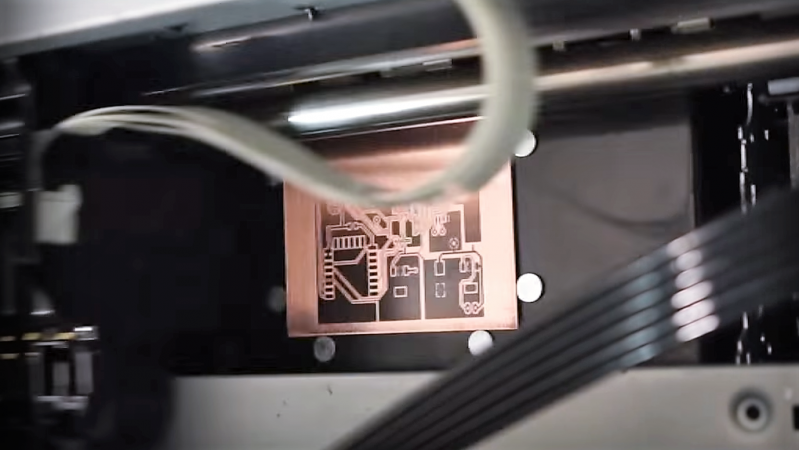
Sometimes we get tips that only leave us guessing as to how — and sometimes why — a project was built. Such is the case with this PCB printer; in this case, the build specifics are the only thing in question, because it puts out some pretty impressive PCBs.
All we have to go on is the video after the break, which despite an exhaustive minutes-long search appears to be the only documentation [Androkavo] did for this build. The captions tell us that the printer is built around the guts from an Epson Stylus Photo 1390 printer. There’s no evidence of that from the outside, as every bit of the printer has been built into a custom enclosure. The paper handling gear has been replaced by an A3-sized heated flatbed, adjustable in the Z-axis to accommodate varying board thicknesses. The bed runs on linear rails that appear custom-made. Under the hood, the ink cartridges have been replaced with outboard ink bottles in any color you want as long as it’s black. The video shows some test prints down to 0.1 mm traces with 0.1 mm pitch — those were a little dodgy, but at a 0.2 mm pitch, the finest traces came out great. The boards were etched in the usual way with great results; we wonder if the printer could be modified to print resist and silkscreens too.
[Androkavo] seems to have quite a few interesting projects in his YouTube channel, one of which — this wooden digital clock — we featured recently. We’d love to learn more about this printer build, though. Hopefully [Androkavo] will see this and comment below.
Thanks for the heads up, [Stephan].


Looks like a UV printer to me. It’s like 10x the size of an Epson Stylus Photo 1390.
“as every bit of the printer has been built into a custom enclosure.”
Because reading is hard
How do you drill the holes? I’ve ways had awful results by hand. Maybe I just bad shoddy and oversize drill bits though.
The easiest way is to use a Dremel press.
If you don’t have a press then use a pin vise to start the hole, followed by the Dremel to drill it the rest of the way. You don’t wanna go straight to the Dremel though as it tends to slip around when you first make contact, starting with a pin vise makes a little divot for the Dremel bit to slip into.
I use a punch to get to dent the centre.
If you’re using KiCad, try the “small holes” option — it does the denting for you. I still hate drilling holes.
What [Elliot Williams] said.
I use small holes and they will guide and center the drill bit when you start drilling. Just use a light force until the drill bit is centered and then increase the force to drill through.
In my CAD I can’t go smaller than 20 mill holes per pads but they seems to work even though I would prefer smaller.
Holes are always the killer for homemade PCBs. I’ve pretty much abandoned homemade PCBs until I build a CNC drill, the results aren’t worth the time and effort the drilling takes.
Word! I have a (manual) XY table on a drill press, and it’s plenty accurate when I provide enough light and squint just right, but it’s tedious.
Putting the whole thing under CNC is somewhere on my to-do list. I order out when there’s more than 30-40 holes.
I hate drilling, too, although I made a homemade door hinge drill press to make it easier and to allow the use of surplus carbide PCB bits which are very brittle and would probably snap if used by hand. I minimize the need for drilling as much as possible by using surface mount devices as much as possible. The carbide bits:
https://www.harborfreight.com/20-pc-carbide-rotary-micro-bit-assorted-set-62379.html
Harbor freight used to sell them even cheaper and in much larger assortments. Still, $8.99 for an assortment of 20 bits isn’t bad. Exactly the same assortment is being sold on Amazon for nearly 3 times the price and on eBay for nearly twice the price.
My trick was to mount a webcam facing up under the plate on a cheap drill press. I line-up a marker on the screen where the drill bit is located when in the “down” position. I then place the work to be drilled upside down and drill it from the back. The camera can be zoomed for very precise drilling. Not fast, but good for DIY one-offs.
Very neat trick!
A drill press is essential. Also print small ( 0.5mm) holes at the pad centres, when etched these help centre the drill.
Use a Dremel tool in a Dremel drill press to drill the holes prior to etching.
:
That’s a rather neat project !
Wonder if you could put boards in a second time for a solder mask ink, then a third for markings.
Is there a type of ‘thinset’ masking out there that could be jetted?
Solder masks aren’t really doable with LASER and probably heated bed ink jet but the results aren’t as good as you would like as they will burn up quickly with the heat of soldering. Toners melt in the range 165 to 200 deg Celsius (329 to 392 Fahrenheit) and soldering (60/40) starts at about 270 Celsius (518 Fahrenheit) upwards.
Overlays are more effective but have limitations too. Printers us subtractive printing where you start with a “white” media and print the darker colors unlike a true overlay that can be printed in white. The other issues is that toner or ink isn’t very mechanically stable so it needs to be coated over with something like a clear acrylic spray paint.
0.1mm traces are narrower than most inexpensive board houses will do. Getting good results at 0.2mm on a home setup is amazing!
Is it possible to do this with a laserjet?
Ideas…
Next question- CMYK Silkscreens?
As laser printers use electrostatic charge on the paper (that’s the only thing the laser does) to make the toner stick to the right places, it will certainly not work on conductive surfaces such as copper.
I was able to print directly on flex pcb substrate with laser through regular paper path. Use thick stock setting and max powder density
That’s interesting. I don’t get how it could works, thou. Can the laser charge the flex PCB underneath the copper?
You just put the “board” as if it was regular paper and etched what came out?
Also, where did you get the flex copper clad?
If you could share a bit more about this method (precision? some pictures?), it could be a new great way to make PCBs.
https://www.youtube.com/watch?v=Qdp7XvlEfbY – this is for aluminium foil.
It looks like a bog-standard DTG-printer just modified with a heated bed. Nothing “new” here.
Yes, it does. Though that’s an EXPENSIVE printer to sacrifice for making PCBs.
It’s more expensive than you think.
Epson printers measure the amount of ink printed and will irreversibly stop once some limit is reached. They *say* that it’s because the waste ink reservoir gets full, but a) often times the reservoir can be seen to hold a lot more ink, and b) you should be able to remove and replace the reservoir anyway.
Once the printer has reached EOL you have to literally throw it out – no amount of futzing will fix it. You can *purchase* a firmware resetter for the printer, but that only allows you to complete the print job that you were in the middle of when the printer decided it was EOL.
I’ll never use or deal with an Epson printer again – too many bad experiences of the printer going irreversibly EOL after putting a ton of work into it.
The reservoir tank is usually removable, as a full blown disassembly repair process. (My office-grade Epson has one that’s externally replaceable) Part of the problem is that there’s no real sensors on any of this and Epson just operates closed-loop assuming that every firing of the nozzle during a cleaning cycle is going into the diaper and counts them. Ink cartridge capacity is determined the same way (plus a slop factor they got sued for having) hence the chips on the cartridges. As for reliabilty? Epsons use a piezoelectric print head that in theory is more durable, but is also not normally replaced, so anyone who isn’t printing color pretty constantly has ink dry out in the print head that has to be wasted by actuating the nozzles directly into the diaper system and a miserable time as you discovered.
As wide-format Epsons go this particular model was a relatively cheap choice, and old: probably used or just already on hand.
A closed-loop system would have a sensor to detect when the reservoir was actually full; just counting the nozzle firings is open-loop.
Count me among the “Epson printers don’t work well for me because I don’t print often enough” crowd.
You can unofficially find maintenance/reset softwares on the web. I have successfully reset mine.
Beautiful. Awaiting a cheap Chinese ripoff of the idea. Toner transfer until then.
sign me up for CNC. even drills the holes.
Apparently it’s not custom built, if you look for “epson 1390 flatbed” on google or youtube, you’ll find out that this printer is sold for around 2000$.