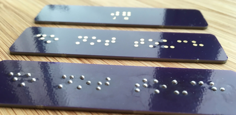
[jg] recently passed some damaged Braille signs and took on the challenge of repairing them. Informed by his recent work on PCB lapel pins, [jg] immediately thought of using circuit boards for this project. He’d noticed that round solder pads made for uniform hills of solder, and this reminded him of the bumps in Braille.
He began by reading up on the standards of the Braille Authority of North America, which stipulates a dot height of 0.6mm. He loaded up the PharmaBraille font system and laid it out the dots in photoshop, then and imported it into KiCad and laid out the boards. When the PCBs had arrived from OSH Park, [jg] soldering up the pads (lead free, but of course) to see if he could get the hills to 0.6mm. He’s experimenting with different methods of melting the solder to try to get more even results.
Braille interfaces crop up a surprising amount in hacker projects. This refreshable Braille display and keyboard and the Braigo LEGO Braille printer are prime examples.
[thanks, Drew!]


That’s a really cool, novel idea.
Now have tracks connecting the dots to a circuit that activates some extra functionality.
Cap-touch sensors in the letters are the braille equivalent of eye tracking for written words.
What about a theramin like thing that changes pitch the closer you get to the dots that helps people find them.
someone i worked with actually did this to leave his mark, never thought about using it for a practical purpose
He should add a via in the pad to mechanically connect it to the other side of the board, as it is you could scrape those pads off with a credit card if you wanted.
Soldermask-defined pads would solve that problem as well, without tending to drain solder out and produce inconsistent bumps. Just leave the board fully covered in copper and create the dots in the solder mask layer only. It would be harder to solder with an iron, though — preheating or whole-board reflow would be almost a requirement.
At last a use for lead free solder!
exactly :)
or add a layer of paint/epoxy
Better clean it really well then. I’ve heard that the flux in many lead free solders is more toxic than the lead in the good old stuff!
A layer of spray paint over the whole thing wouldn’t be a bad touch either although I wouldn’t rely on that entirely to seal in the bad stuff as it might wear through with time and use.
I’d be looking at how they achieve spec on BGAs.
I’d also think there’s some magic between pad size and surface tension of the particular solder alloy when molten.
Solder upside-down and limit how much solder you use on each pad.
Or try dipping the PCBs upside-down in a solder pot and let pad size determine the height.
I think adhesion is stronger than gravity in this application. Certainly if there were vias the capillary effect would be stronger than gravity.
What a nice application for PCB technology, cool project!
A solution that introduces more problems: now you have to order the PCBs from somewhere, but they don’t come finished and you have to solder them yourself.
If you have to work them by yourself, you might as well use a pin and a hammer on some brass plates.
Trouble is Braille is “up”, not “down”, really difficult to do uniformly with hand tooling.
You can use a stencil to apply the solder and reflow in an oven, which should produce more uniform results…
You put the brass plate on a piece of felt and hit the pin with the hammer. One side goes down – the other side goes up.
And you can also achieve consistent height for the bump by having a shoulder on the pin you use to strike the dots.
@Dex, I think you are right.
Maybe this could be a cool trick though if it were integrated into something else. I am still thinking of what though.
My first thought was to use it to add markings to a capacitive touch control. But.. you probably wouldn’t want Braille labels and capacitive controls in close proximity or blind people would be making things happen by accident.
Maybe as part of a display PCB? But.. having a display on a PCB kind of indicates that it displays changing contents. If not, then why the electronics? One could just paint static text on. The Braille of course is unchanging so it doesn’t really compliment an LCD, LED or etc…
Ok, cool trick but I give up. Somebody else please find a good application!
As ever, we can rely on Dax being obnoxious.
At the high school I went to I was curious how hard it is to distinguish the dots on the braille door signs. I rubbed my hand on it and all of the dots fell off.
I think this is first time putting lead-free solder on a PCB is actually a good idea.
Also radiosondes.
I just wanted to say thanks to JG. This project was a big inspiration for something I’ve been working on. The solution I found for getting really even height on the braille bumps is to cut pieces of solder to a specific length, stick them to the pads with a bit of flux, and hit them with a blow torch (gently!) until they pool and ball. Bit tedious when doing it by hand, but I’m looking into the possibility of reflowing with large solder balls next. Also, I was tickled to discover that braille and breadboards have the same spacing. Fun little coincidence!