How would you sell a computer to a potential buyer? Fast? Reliable? Great graphics and sound? In 1956, you might point out that it was somewhat smaller than a desk. After all, in those days what people thought of as computers were giant behemoths. Thanks to modern FPGAs, you can now have a replica of a 1956 computer — the LGP-30 — that is significantly smaller than a desk. The LittleGP-30 is the brainchild of [Jürgen Müller].
The original also weighed about 740 pounds, or a shade under 336 kg, so the FPGA version wins on mass, as well. The LGP-30 owed its relative svelte footprint to the fact that it only used 113 tubes and of those, only 24 tubes were in the CPU. This was possible, because, like many early computers, the CPU worked on one bit at a time. While a modern computer will add a word all at once, this computer — even the FPGA version — add each operand one bit at a time.
The LGP-30 had a Friden Flexowriter (a TeleType-like machine made by a company eventually bought by Singer, the sewing machine company) and a magnetic drum with 4096 32-bit words. To keep the component count down, the drum stored the program, the CPU registers, and even the 120 kHz system clock. There were also 1,450 solid-state diodes, which helped. To avoid building a lot of blinking lights, the front panel had an oscilloscope that displayed three registers. There were about 500 units sold for about $47,000.
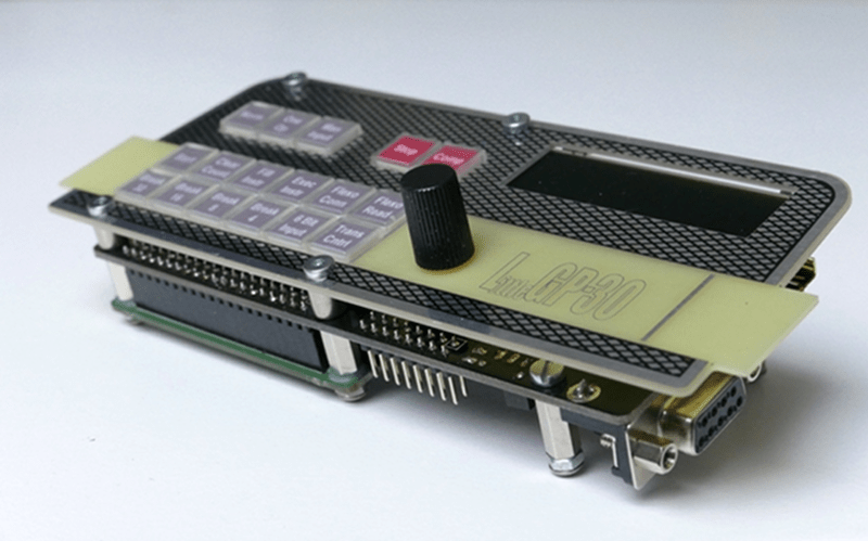
The FPGA version — mercifully — is less expensive. It uses a Xilinx Spartan 6 development board and a custom PCB that even duplicates the oscilloscope on an LCD. You might notice some strange characters on the oscilloscope. Even though the computer used hexadecimal (which was unusual in those days), it did not use A-F for the extra digits. Instead, it used characters that were easier for the limited hardware to decode: f, g, j, k, q, and w. So 255 in LGP-30-speak is ww not FF.
Although the FPGA version is faithful, inexpensive, and small, it isn’t the first solid-state version of the architecture. Librascope — the company behind the LGP-30 rolled out the LGP-21 in 1963 which had less than 500 transistors and 300 diodes. It wasn’t as fast as the LGP-30, though, and cost a measly $16,200. Then again, the FPGA board costs less than $40 although the front panel and case will move that price up, it is still going to come in well under that price. If you want a peek inside the real machine, check out the video below.
Any time we see bit-serial CPUs, it reminds us of EDSAC. One thing that was interesting to us was that a 113 tube machine would have been within reach of the day’s hackers if they’d had the plans. In 1967, for example, people did build the Wireless World Computer with around 400 transistors.


“How would you sell a computer to a potential buyer? Fast? Reliable? Great graphics and sound? In 1956, you might point out that it was somewhat smaller than a desk.”
I remember when MINI-computers were about that size.
Did you know that ‘Mini’ came from ‘minimal’, not the size of the computer?
I figured it was a size-is-relative kind of thing. My old ZX Spectrum microcomputer was visible to the naked eye!
It sounds very similar to the Recomp III that I learned to program on, only it was solid state.
ME TOO!! (LGP-30 and Recomp III, that is). In 1961 I was working for GE on the Apollo Study Contract. We had a big IBM 704 mainframe, but my favorite was the little LGP-30. Later we “upgraded” to the Recomp III — also great. As the pictures show, both were “desk” computers. They were, as far as I know, the first single-user, interactive computers, The big machines were, of course, all run by IBM punched cards, so you had to submit your jobs over a counter, and wait hours to get the results back. With the little guys, I could get back results almost as fast as I could hit the RUN key.
Before FORTRAN, all these small computers (and some big ones) used interpretive languages — the precursors of BASIC, I guess. In spite of the small size, all the math was (decimal) floating point, and it included all the usual trig functions, square root, etc.
The LGP-30 used single-address instructions, all in decimal. IIRC, 10 was the opcode for an add, 20 for subtract, etc. There was a special code for functions, and then a function number to specify which one.
The interpreter for the Recomp III was delightful. It used readable character opcodes like +, -, *, /, etc. Function calls were f1, f2, etc. I think that l (lower case L) was for input, o for output. Or maybe l was for load, s for store.
In 1961, we were desperately trying to get trajectories to the moon (I still am, in fact). GE’s N-body program ran on the mainframe, of course, but I used the LGP-30 to work out the geometry. It was a _HUGE_ aid; far more than the size would lead you to believe.
Thanks for the memories.
Damn… try to operate one of those today, and Workplace Health and Safety would be demanding hearing protection.
Many machines still do. Cray XK systems like ORNL Titan have a 5hp blower in each cabinet. Imagine 200 of those in one room all powering up at once.
This is the computer that is the foundation of the “The Story of Mel” https://en.wikipedia.org/wiki/The_Story_of_Mel
A working LPG30 in full size can be seen in action at University Stuttgart http://computermuseum.informatik.uni-stuttgart.de/dev_en/lgp30/lgp30.html.
I’m sure someone out there is working on a 2-bit computer, called “Shave And A Haircut”.
I’ll suggest that, next time someone asks for an FPGA project.
Correction: On the Recomp III, i and o were input and output, l and s for load and store. On both machines, you had to specify the variable addresses manually. No such thing as a symbol table. So to add two numbers, you might write
i 1000
i 1001
+ 1000
s 1000
o 1000
Or something like that.
Someone got a real one of these working – http://computermuseum.informatik.uni-stuttgart.de/dev_en/lgp30/lgp30_3.html
The CRT display looks interesting –
http://computermuseum.informatik.uni-stuttgart.de/pics/lgp30/senter3k.jpg
I wonder if the bit-serial streaming of it’s operation is synched in with the scanning of the oscilloscope’s beam, so each bit is drawn on screen as it goes through the processor? I’d bet it is, and I’d bet it’d be a pain in the arse to do!
Yes, that’s pretty close. The traces on the scope show the three CPU registers (accumulator, instruction register, and program counter). They are drawn in sync with the bits passing below the read heads of the magnetic drum. That’s the only way to do it, because you don’t have those bits available anywhere else! And that’s why they did use an oscilloscope, rather than a row of lamps: You need a display which is inherently bit-serial for this CPU design.
As a side note, the beam in the little oscilloscope scans from right to left: On the drum, data are stored low-bit-first (necessarily, to enable a carry bit during calculations). And on the display you want to see the low bit on the right (to present binary numbers to the user in the conventional way).
24 tubes is amazing! Although I wonder if that’s not something like the ULA, with the other 89 helping instruction decode and machine state and stuff. Otherwise I can’t think what you’d need 89 tubes for when the CPU’s only 24.
Very impressive. I bet they had to think round some weird angles to get that into reality. Sort of thing like Woz’s Breakout, where if you didn’t know how it worked, it’d be simpler to design a new one from scratch than try figuring it out.
“it’d be simpler to design a new one from scratch than try figuring it out”
Me when when told to revise a program with poor documentation.
“24 tubes is amazing! Although I wonder if that’s not something like the ULA, with the other 89 helping instruction decode and machine state and stuff. Otherwise I can’t think what you’d need 89 tubes for when the CPU’s only 24.”
No, there’s no cheating regarding the 24-tube count. Thats all that is needed to decode and execute instructions, inclluding an ALU whch does 32 bit multiplication and division in hardware! The other 89 are used to address and drive the read/write heads of the magnetic drum, and to drive the Flexowriter terminal.
The 24 tubes implement 15 flip-flops, 6 inverters, and 6 cathode followers (to amplify signals driving multiple inputs). That’s right, only 15 flip-flops, i.e. only 15 bits are held electronically at all. It does help that the CPU is a bit-serial design and relies heavil on the magnetic drum memory. Not only the main memory, but also the three CPU registers live on the drum.
Thanks to Hackaday for featuring my “LittGP-30” replica, by the way!
So how does it do logic, eg addition, with 6 inverters and 15 flip flops? Is this all written up on your website? I’ll have to have a look. Is there some kid round the back with a bunch of torch bulbs and paperclips?
Essentially the CPU is a small state machine, triggered by the bits on the magnetic drum as they pass by the read heads. In addition to the tubes, there are quite a few AND and OR gates implemented in diode-resistor logic. (Solid-state Germanium diodes were already around and robust enough for commercial use. Hence AND and OR were cheap, but negation was expensive, as it required a tube.)
Stan Frankel, the designer of the LGP-30, has published a paper in 1957 which explains the CPU in loving detail:
http://radar58.com/LGP30/wp-content/uploads/2017/01/Frankel.pdf
Why exactly does the LGP30 use f, g, j, k, q, and w? Each pair e.g. f&g, j&k and q&w are next to each other on the keyboard, so it may have something to do with the key matrix of the keyboard.
Wikipedia apparently needs a citation an that too:
>Unlike other machines of its day, internal data was represented in hexadecimal as opposed to octal, but being a very inexpensive machine it used the physical typewriter keys that correspond to positions 10 to 15 in the type basket[citation needed] for the six non-decimal characters (as opposed to a – f) to represent those values, resulting in 0 – 9 f g j k q w, which was remembered using the phrase “FiberGlass Javelins Kill Quite Well”.
That’s just how the character codes fell on the “Flexowriter” terminal. This was before ASCII, and the 6-bit Flexowriter code was a bit funky. It did not have separate characters for “one” and “lower-case L”, for example — why waste a code, these look the same anyway! ;-)
When entering machine code statements and constants on the LGP-30, the lowest 4 bits of each character were directly rolled into the machine’s accumulator. “A” was the opcode for “add”, for example, and “S” for “subtract”. The character codes on the Flexowriter were chosen to make instruction decoding easy. (Addition and subtraction are very similar operations, so their opcodes differ only by one bit to simplify the CPU architecture.)
That meant that no nice sequence of characters was left for the upper hex digits… At least the character codes for 0..9 were chosen wisely, so their low bits work as the respective hex digits!
You’re saying the LGP and the Flexowriter were somehow designed in concert? Or that Friden designed their character code with those coincidences built-in, as a favour to some future CPU designer who might appreciate the coincidence?
This seems like a very strange machine.
The Flexowriter was designed and produced by a separate company (Friden). Various computer manufacturers used the Flexowriter as a terminal, and Friden did indeed supply various versions with customized code sets.
And yes, this IS a strange machine. It is from an age where “modular design” was not yet a thing. Instead, the designer was proud to have the CPU logic, magnetic drum and Flexowriter interlinked as tightly as possible. If it helped to save a tube or an instruction cycle, every trick or shortcut was welcome! ;-)
Ah, a customised code, that makes sense, didn’t know they were available. I suppose in the early days, why not? Friden would have just had to use a different type head, or decoder mechanism, or whatever.
And it seems like the machine had a certain amount of mechanical parts in it’s operation, if the drum encoded instruction sequencing etc. Extra tracks are cheaper than valves!
Thing about diode or resistor logic, is I thought you needed one active element (ie valve or transistor) per gate. You can build an AND or OR with as many inputs as you like, each one is just an extra diode. But don’t they need an amplifier, or buffer, to keep them from just melting into one big mess of an analogue circuit? Not literally melting, of course, but a load of resistors connected up end up acting like one big resistor. Or seven-thirds of 2-and-a-half resistors. The separation between logical states starts to diminish, currents can flow both ways.
I suppose you can get away with missing out some of the buffers, for a gate that has some positive and some negative elements, a gate that’s a combo AND / OR gate.
Maybe the drum did a bit of logic too. I’ll have to read the link you posted. Again, interesting machine! Amazing what you can boil something down to, from high-level abstraction into actual voltages and currents.
The numerical order of the keys was probably 0,1,2,3,4,5,6,7,8,9,f,g,j,k,q,w etc as it was before ASCII so they just used that instead of what we now know as HEX.
HEX => LGP30
0-9 0-9
A f
B g
C j
D k
E q
F w
Before ASCII? Whose code is that? TELEX? Why would you design such a weird code where FGJKQW are in order instead of ABCDEF?
Reminds me of old russian Elektronika MK programmable calculators. Those probably had different reasons for that, though.
Calculator logic itself crunched numbers in BCD format, but it also was able to display a word “Error” on its 7-seg display. Letters “E”, “r”, “L”, minus sign, space and something else that I forgot, all were mapped in for the remaining 4-bit HEX codes. But then when the newer MK61 was released which was able to do bitwise logic, things got *really* freaky :)
I’ve actually seen this replica at the VCFB a few month ago and had a little chat with Jürgen Müller. Pleasant chap, great project!