While down here there’s room for debate about the suitability of 3D printing for anything more serious than rapid prototyping, few would say the same once you’ve slipped the surly bonds of Earth. With 3D printing, astronauts would have the ability to produce objects and tools on-demand from a supply of inert raw building materials. Instead of trying to pack every conceivable spare part for a mission to Mars, replacements (assuming a little forward thinking on the part of the spacecraft designers) can be made to order out of the stock of raw plastic or metal kept on-board. The implications of such technology for deep space travel or off-world settlement simply cannot be overstated.
In the more immediate future, 3D printing can be used to rapidly develop and deploy unmanned spacecraft. Tiny satellites (referred to as CubeSats) could be printed, assembled, and deployed by astronauts already in orbit. Innovations such as these could allow science missions to be planned and executed in months instead of years, and at a vastly reduced cost.
Early Successes in Space Printing
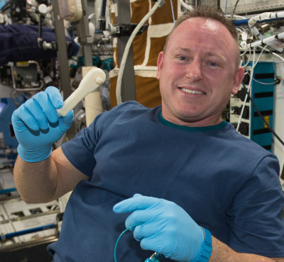
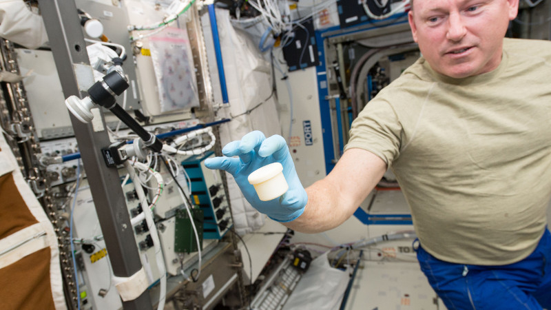
You may not realize it, but as you read this (well, assuming you aren’t reading this past 2025 or so), a 3D printer is in orbit above our planet. Designed and built by Made In Space, and launched aboard a SpaceX Dragon capsule in 2014, the International Space Station’s 3D printer has already printed a number of test pieces that have verified the fundamental concepts of Fused Deposition Modeling (FDM) 3D printing in orbit. In other words, the same technology used in our run of the mill desktop 3D printers has now been used to turn plastic filament into legitimately useful parts and tools for a manned orbital spacecraft.
For NASA, the success of this first-generation 3D printer is a huge win. In the future, it should be possible to use this same technology to limit the number of spare parts and tools that need to be painstakingly cataloged and packed for every human mission into space. As NASA is currently turning its attention to a return to the Moon (either on the surface, or in orbit around it) and eventually onto Mars, this could be a huge logistical boon. NASA has even awarded Made in Space a contract for developing a filament recycling device, which could crush up printed objects and turn them back into filament; further reducing the need for resupply missions from Earth.
Developing a Printable Spacecraft
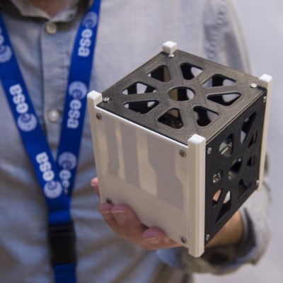
While NASA is largely interested in the viability of 3D printing objects off-world, other groups such as the European Space Agency, are looking into how 3D printed parts can be utilized in the construction of spacecraft. Using 3D printed parts can not only lower the cost and complexity of developing new vehicles here on Earth, but also directly benefits from work being done to print in space.
By developing printable frames for CubeSats, the ESA hopes to one day enable the manufacture of these small craft in orbit. Rather than subjecting these fragile spacecraft to the mechanically stressful launch from Earth, these CubeSats could be assembled from modular components and printed frame members by the astronauts themselves. Once assembled they can be “launched” by literally throwing them out of an orbital installation such as the International Space Station. Printed out of polyether ether ketone, better known in 3D printing circles as PEEK, these CubeSat frames also include conductive elements to reduce the amount of wiring required to connect the various subsystems contained within the satellite.
CACTUS-1 Mission
Thanks to the precipitous drop in launch prices (due to increased commercial competition from the likes of SpaceX) and the relatively low cost of CubeSat hardware, Low Earth Orbit (LEO) is no longer the domain of world superpowers alone. Private industry and universities are now able to launch and operate their own orbital satellites, and these groups are also eager to investigate the use of 3D printed components to reduce the cost and development time of these small space vehicles.
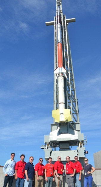
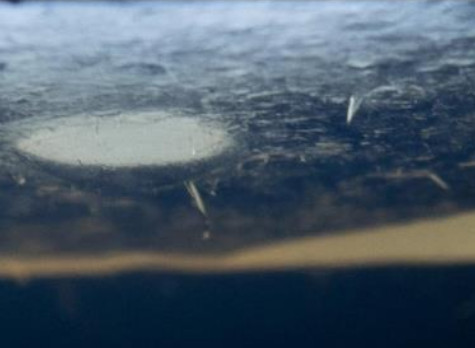
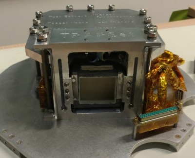
A team from Capitol Technology University in Maryland are in the final stages of developing their CubeSat, the Coordinated Applied Capitol Technology University Satellite (CACTUS-1), which aims to demonstrate several cost-saving measures when it launches on the NASA ElaNa XX mission in 2018. It uses off-the-shelf components such as a Raspberry Pi and Iridium satellite phone modem to accomplish tasks which in the past would have been done with expensive custom hardware. The primary science payload on CACTUS-1 is called TRAPSat, a subsystem designed to capture orbital micro-debris in a block of aerogel and analyze them in an effort to better quantify the danger they pose to vehicles operating in LEO.
We recently had the opportunity to speak with members of the CACTUS-1 team about their unique mission, and gain some insight on how 3D printing became such a key aspect of the vehicle’s development.
Hackaday: Thanks for taking the time to answer some of our questions about CACTUS-1. To start with, can you introduce yourselves and give the readers an idea of your roles in the mission?
Mike: My name is Michael Strittmatter, I graduated from Capitol Technology University (CTU) with a Bachelors in Management of Cyber and Information Technology. I am the Subsystem Lead of the TRapping with Aerogel Prototype Satellite (TRAPSat) subsystem on the Coordinated Applied Capitol Technology University Satellite (CACTUS-1) Mission a 3U ++ tab configured CubeSat Mission based out of Capitol Technology University in Laurel Maryland as well as a Systems Engineer on the TRAPSat program.
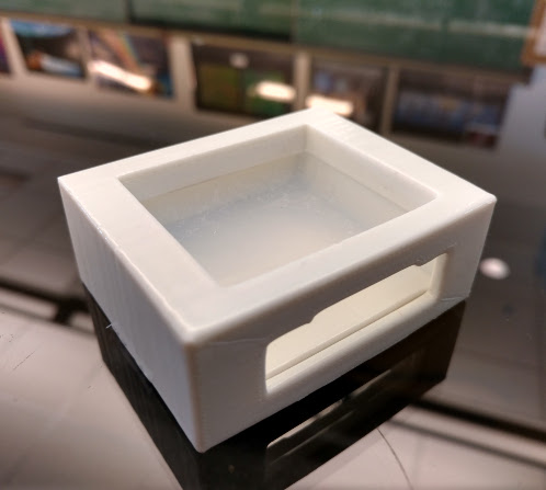
I have been a part of the TRAPSat program for over 3 years and worked on developing the camera subsystem that takes photos of our aerogel capture medium as well as 3D print the prototypes and flight parts for the mission. Our main 3D printed part that I print is our Removable Aerogel Support Container (RASC) which is a container that protects and supports our silica aerogel monolith from outside damage.
Ryan: My name is Ryan M Schrenk, I graduated from CTU with a Masters in Astronautical Engineering. I am the founder of the TRAPSat mission as well as the Co-Principal Investigator and Lead Systems Engineer for the CACTUS-1 Mission. I have been working on TRAPSat since 2013 when I was an undergrad at the then Capitol College. Throughout the years I have led the ever evolving team through high altitude balloon missions, sounding rockets, and now culminating to our now orbital mission.
What are the advantages of using 3D printing for the construction of CubeSats like yours compared to traditional manufacturing techniques?
The advantages of 3D printing is that is allows teams to rapidly prototype their designs over multiple iterations, reduce build times, and save money on material, shipping, machine time. It allows teams to go from an on paper concept to a physical pro-type in days compared to months. It allows teams who don’t have the resources to get parts professionally milled a way to build and test prototypes. Lastly since our mission is measured in months, materials don’t need to withstand the harsh environment of space for long.
What purpose do the 3D printed parts on your CubeSat serve?
They house our aerogel. This allow us to insert and remove our aerogel from our CubeSat without contamination or damage. It also allows us to reuse the same aerogel monolith on multiple high altitude missions. Lastly it protects the aerogel from breaking due to the harsh launch environment.
It seems that previous 3D printed parts used on spacecraft have always been non-essential components. Will your mission be the first to use 3D printed parts in a mission-critical application? How do you feel about potentially being the first to hit this milestone?
Although this part is critical, we don’t feel that this qualifies as the first critical component to be printed for space. However if it is…cool. NASA has already claimed that this mission is the first CubeSat based orbital debris detector to be flown in LEO and that is enough for us.
What printers were used to manufacture your parts? Were you able to do any of the printing in-house?
Mike: I own an Ultimaker 2 to manufacture our parts. So yes all of our printing was done in house. I print all of our parts at a .06 mm resolution at a 80% infill and print at 60 mm/s .These settings may be overkill but have proven effective. Plus, who doesn’t like smooth prints?
The ESA has been experimenting with printing CubeSat frames in PEEK. What type of plastic are your printed parts made of, and how did you decide on it?
Mike: We have experimented with a few different types of material from PLA, ABS, and Co-Polyester. We print all of our parts using Clear PLA because of its low out gassing properties.
Ryan: From a mission planning perspective, when picking material we looked at our mission life and decided that our short mission life did not require a material that can hold up for years in space.
Those familiar with desktop 3D printing will probably be surprised to see you settled on PLA, are you using any special treatment or post-processing on the parts to make them space-worthy?
Ryan: To make our parts space-worthy we sand down the prints to ensure a custom fit for our aerogel. All external surfaces with Dow-Corning 734 RTV to reduce vibration on the aerogel and protect the RASC from the environment. We then clean the parts in alcohol and fit the aerogel into the RASC.
What are your biggest concerns for your printed components when exposed directly to space? Which failure mode do you think is most likely, if any?
Our biggest concern would be structural degradation due to radiation or extreme thermal loading over a long period of time.
Assuming a successful mission, what’s next?
We would love to go bigger and add more more features such as impact sensors, larger collection surface area, and better cameras to image the aerogel.
Are there any particular tips or words of advice you’d give other teams that are considering using 3D printed parts in their CubeSats? Or advice for potential CubeSat builders in general?
Any team that needs to move from the think tank or drawing board to hands on prototypes can benefit from 3D printing. Also when you only need to design or test something one time, it is much cheaper and faster to create a one-off production to save money and time. 3D printing can be utilized to replace older, slower and costlier manufacturing techniques, speeding up production.
Once a mission is planned and the constraints are known any commonsense engineer can determine if this is an effective solution to their fabrication needs, if not it is still a great prototyping test bed.
As for advice, know your machine tolerances. A lot of students do not take that into consideration when designing parts and that will lead to hours of sanding to get the part to fit correctly. Also learn how to be adaptive with your team. A lot of CubeSat teams are college students and missions iterations are usually a semester long with students coming and going. By establishing good documentation practices it will allow a team to have continuity over numerous years. Always use the KISS, Keep it Simple Stupid method. The less moving parts the better although it looks cool, means higher failure rates. Lastly have a solid project scope, scope creep is a real thing that can kill a mission. By having a solid and well defined goal, a mission will not get out of hand.
Thanks to Mike and Ryan for taking the time to answer our questions and providing so many fantastic images. The Hackaday Team wishes them the best of luck with their 2018 orbital mission.



“The implications of such technology for deep space travel or off-world settlement simply cannot be overstated.”
The Bobiverse series uses this to good effect.
Allow me to add…
Dennis E. Taylor (Author), The Bobiverse, a “Hard Sci-Fi” 3-book series:
* We Are Legion (We Are Bob) (Bobiverse, #1)
* For We Are Many (Bobiverse, #2)
* All These Worlds (Bobiverse, #3)
Links to all three:
https://www.goodreads.com/series/192752-bobiverse
I love these books so much, I’m happy to see I’m not the only one!
And here I’m still trying to achieve reliable printing down on the surface!
Lovely article, definitely interesting and promising. But anyone who thinks you can launch a satellite by throwing it out the ISS airlock needs an orbital mechanics primer. Unless it has its own propulsion system, that satellite will be coming right back to you like a boomerang. Potentially a dangerous situation.
In theory you are correct, and yet that is precisely what they do:
https://www.space.com/26841-spacewalking-cosmonaut-launches-peru-satellite-video.html
Keep in mind that not only are you imparting momentum on the CubeSat by the initial toss but that it will begin slowing down as it has no capability for reboost. Between initial “kick”, atmospheric drag, and Kepler’s second law (objects closer to Earth will orbit faster than those farther away), there is enough variables that the orbits of the ISS and deployed Cube will never intersect again.
Surely only correct if you threw it out of the airlock, in the same direction the ISS is travelling? Throwing it out of the ‘back’ airlock would cause it to ‘follow’ the ISS, but it’d never catch up due to lack of propulsion?
Throwing it out the aft airlock will cause it to end up ahead of the station. Orbital mechanics is a bit weird until you get used to it.
If you assume the ISS is in a circular orbit, then throwing the cubesat out the back means it’s no longer going fast enough to stay in the same circular orbit as the station. It will now be in a slightly elliptical orbit, with a perigee below the ISS’s orbit and an apogee at the same altitude as the ISS.
That orbit has a shorter period than the station’s, so the cubesat goes around its full ellipse and reaches its apogee (the same location where it was ejected) before the ISS completes its orbit and also reaches that same point.
An astronaut watching this from the cupola will see the cubesat initially depart the station to the rear, drop toward Earth, swoop forward ahead of the station, then climb back up to the station’s altitude in front of the station. In the absence of drag, this would repeat with each orbit putting the cubesat further in front of the station.
But drag is a thing at that altitude, and the cubesat’s larger area-to-mass ratio means its trajectory is altered by drag more rapidly than the station’s is. The drag will reduce the cubesat’s altitude and (paradoxically until you’ve done the math) increase its forward speed relative to the station.
Without drag, the cubesat would eventually step ahead of the station until it crept around an entire orbit and risked a collision, but that takes so long that drag will have long since separated their orbits. The ISS also conducts re-boost maneuvers every now and then, which further separates the craft.
That was a spectacularly concise reply. Totally learnt something new just there – cheers.
I now feel like a knowledgeable orbitologist- thanks!
I too play Kerbal Space Program.
Good point. I’m surprised it loses that much velocity after only half an orbit, though. They should intersect again at that point, only around 45 minutes later.
Additionally it sounds like this one was launched via spacewalk, which adds some more offset to the orbits.
Does the ISS need to reboost every 45 minutes? If it doesn’t, the cubesat would actually lose less velocity due to lower drag.
To put some numbers to the situation I described in my other comment, let’s say the ISS is in a circular orbit at 400 km altitude, and the cubesat is ejected at 2m/s directly retrograde. That places the ISS’s speed at 7668.5 m/s and the cubesat’s apogee speed at 7666.5 m/s.
The cubesat’s orbit is now elliptical, with a 400 km apogee and a 392.9 km perigee. The astronaut will see the cubesat pass about 7km below the station, going about 8m/s forward relative to the station. It doesn’t reach its minimum altitude until it’s well ahead of the station, though. (I’m not bored enough to calculate exactly how low it is when it goes directly below the ISS, sorry.)
This orbit has a period of 5549.3 s, compared to the ISS’s period of 5553.7 s. That means the cubesat will reach its apogee, which is also the point where it was ejected from the station, a bit more than 4 seconds before the station reaches that same point. Being earlier than the station means it’s leading the station in orbit, by about 33 km in this case.
With each orbit moving the cubesat 33km ahead of the ISS, it would take 1290 orbits for the cubesat to lead by one complete orbit and again have a chance to get close to the station. That’s about 82 days, by which point the cubesat’s orbit will have decayed by at least a few kilometers due to drag (also changing its orbital period and invalidating the drag-free calculations). There’s a good chance that the ISS will have re-boosted within that time as well.
If an Aussie astronaut threw it.
So this completely ignored the fact that many parts on new rockets are fully 3d printed in nitiol. Parts such as the turbo pumps, and fuel manifolds on the falcon 9 space craft.
Do you mean nitinol, or are you referring to a different material? If they are using nitinol, I wonder how the shape memory effect impacts the behavior of the parts. More importantly, why did they choose nitinol in the first place? Does it have properties that make it easier to to sinter into a usable part? If anyone knows, I would love to find out.
I think you are confusing a number of things here.
SpaceX is printing the combustion chambers of the SuperDraco engines out of Inconel. As of yet these engines have never flown, but will be a critical component of the future crew-rated Dragon V2 capsule.
The Falcon 9 is not a spacecraft, but a booster rocket. We could say it gets honorable mentions as the Merlin engine does use a 3D printed main oxidizer valve, but the turbo pumps and manifolds on the Merlin are not printed.
NASA is experimenting with a 3D printed turbopump for future engines and missions, but again that has never left the test stand.
“My name is Michael Strittmatter, I graduated from Capitol Technology University (CTU) with a Bachelors in Management of Cyber and Information Technology. I am the Subsystem Lead of the TRapping with Aerogel Prototype Satellite (TRAPSat) subsystem on the Coordinated Applied Capitol Technology University Satellite (CACTUS-1) Mission a 3U ++ tab configured CubeSat Mission based out of Capitol Technology University in Laurel Maryland as well as a Systems Engineer on the TRAPSat program.“
Wow!
That’s A Lot Of Capitalization.
Ostracus, thanks for the book name, good one! :)
In response to the first sentence of this article, I find that people (businesses) don’t think 3d printing is suitable until we tell them that it is. At the company I work for, we routinely save local (and not so local) businesses lots of cash when we show them that this 3d printed part we have made for them works just as well as the one made by more traditional processes.
Interestingly, Lyra Levin (who also headed up mech-e at Megabots) contributed to the engineering on this printer http://www.lyralevin.com/engineer#/made-in-space/
The EC0 cubesat from UNSW (part of the QB-50 project) currently in space has a 3Dprinted structure:
http://www.acser.unsw.edu.au/QB50
Was deployed from the ISS in May 2017.
cash price of project total?
Credit to my Alma Mater for this project: https://news.nnu.edu/story/nasa-selects-nnu-for-cubesat-space-missions
3d printing in space = no more need for support material!
cool in my cca class we are going to make something like a person ad a chair
The president of Made in Space is a good friend of mine, he goes nuts over this 3D printing in space stuff. Suppose that makes him a good president for that company haha.
When can we expect to see his interview here on HAD.com?