[Tobias Kuhn] had watched a YouTube video about a robot arm which used servo motors, and wanted to try making one himself. But he found it hard to get slow or smooth movements out of the servos. Even removing the microcontroller and trying to work with the servo’s driver-IC and potentiometer from an Arduino Nano didn’t get him satisfaction.
Then he found the very affordable 28BYJ-48 stepper motor. After some experimenting, he came up with a smooth moving robot arm with four steppers controlled from an Arduino Mega and A4988 stepper motor drivers. Rather than write a bunch of stepper motor code himself, he installed and ran a four-axis fork of grbl on the Arduino, turning it into a stepper motor controller. One minor hitch was that the A4988 motor drivers are for bipolar stepper motors but 28BYJ-48 steppers are unipolar. Luckily he knew of a very simple hack which our [Brian Benchoff] wrote about for turning a unipolar motor into a bipolar motor.
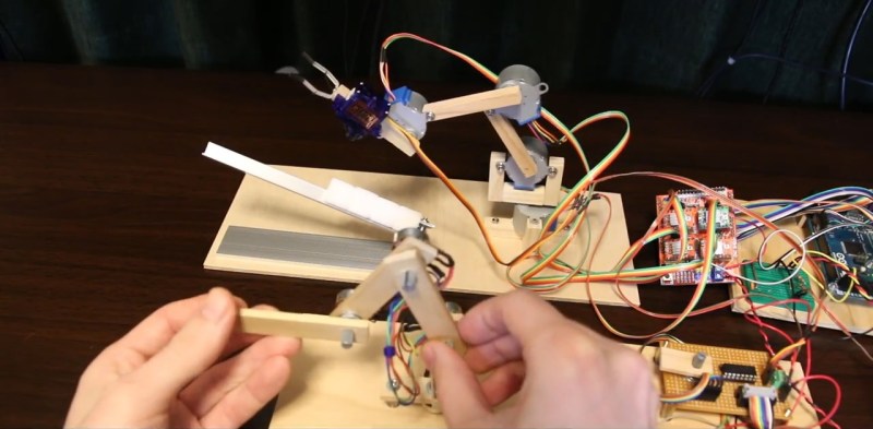
To tell the robot arm what to do, he built a replica arm with potentiometers in place of the stepper motors. As he manipulates the replica, the values of the potentiometers are read by a Raspberry Pi and some custom Python code which sends the appropriate G-code to the Arduino/grbl controlled robot arm. There’s a bit of a lag but when he moves the replica arm, the robot arm does the same move. See it in action in the video below.
[Tobias Kuhn] ‘s robot arm isn’t the only stepper-driven smooth mover we’ve seen around here. Check out this one with an added side-by-side comparison with a rather sharply moving servo motor-driven robot arm.


This is REALLY good, but I’ve expected smoother. Like cubic interpolation of position, not linear with pauses to stabilise arm. Yeah, “show us what you’ve got” applies to me too, I’ve got 3d printer last week so expect my electromagnetic muscle to work soon(ish).
Fun project to keep everyting cheap and minimalistic.
And those are going to be about the cheapest geared steppers you’re likely to find.
( USD 2 or less from Ali / Ebay, including ULN2003 driver).
This has much more potential than anything built on RC servo’s such as the meArm.
And steppers can easily be scaled up to “quite big” without spending too much money.
This can easily be used as first experiment before upgrading to something like the AR2.
By recording more intermediate positons you’ll get more smoother movements.
Shame grbl does not support circles, adding circles in the corners instead of full stops would already be a great additon to make nice smooth transitions.
Some way of dumping the potmeter coordinates to a PC (in G code or alike) and being able to edit it would also be nice.
But the hardware is good enough to start exting experiments with the robot workbench in FREEcad (not so well maintained) or with ROS industrial.
Thumbs up & Kudo’s.
I like it.
G2 and G3 are supported in grbl. Not sure what you mean by “Shame grbl does not support circles”
yes, this is the most minimalist of this type of arm I’ve seen, its basically just the motors and some straight pieces of wood, so simple, no unnecessary fittings or clutter.
I just read the hackaday post from 2014/07/29/changing-unipolar-steppers-to-bipolar/ about modifying these motors.
There is a lot of nonsense in the comment about unipolair / bipolar motors etc.
With the modern driver chips there is no need to ever use a unipolar stepper on purpose.
A bipolar motor uses all the copper in the motor, unipolar motors do not use all the copper (at the same time) and have therefore less performance. It’s simple as that.
When ordering these motors from Ali for experimenteng there are some things to watch out for:
1). They have different gear ratio’s. Sometimes 1:16 is quoted, sometimes 1:64.
2). They come in different voltage ratings. 5V and 12V.
3). Maybe there are also versions with different pole numbers.
Don’t expect 200 steps/rev for these motors.
When you use them in bipolar mode you always want the “Low voltage” = low inductance version.
A decent bipolar stepper driver will limit (chop) the current correctly and prevent overheating.
High voltage (= high inductance) motors have lower torque at high RPM’s because it takes to much time to push current through a motor with high inductance.
The motor voltage printed on a motor is based on the DC resistance & current rating.
There is noting wrong with using a 24V power supply with a 5V rated motor, as long as you use a proper diver chip.
Combine these motors with a 3D printer pcb (such as Ramps 1.5) and you have almost all the hardware needed to build this funny robot arm.
The fun of open source stuff. Throw some projects together to create something new.
One little thing: The datasheet of the A4988 stepper driver (found on most RAMPS boards) tells you that it is NOT allowed to connect the middle of both coils together as done in these cheap steppers. I’ve opened one up and cut the wire. I’m told that it doesn’t immediately blow up if you don’t do it that way.
Yep. Hackaday.com/2014/07/29/cha… is all about cutting that middle wire on the PCB (Under the blue cap).
Somewhere in the comment over there is the suggestion that cutting the trace is not needed, but it cold wel interfere with proper PWM current chopping. So open yours up and cut the middle PCB trace.
Might need some feedback on the end to detect if things are going well.
And even that it could learn as to what to expect, with some fuzzy interpretation for varying circumstances.
Those are the same steppers in the Micro3d printer. They are designed originally to move the louvers in AC units. For a cheap stepper you can’t get better, but don’t ask for too much precision from them.
Jip, got one. Was impressed about the ability of them!
Already had some fun with the steppers before, and was surprised big times finding out that they were used in a 3D printer! And it works quite well.
For the time, it was a rather cheap printer
Now you’ve got me thinking about a virtual finger, to take shots in Angry Birds. Or Golf Clash.
28BYJ-48 is not a “complete type number”.
While getting a lost a bit on Ali I got the impression that there might be different manufactories making this thing with the same type number. Different labelling, Different stampings from the metal casings and who knows what other differences.
One of the remarable differences is that I found a picture of a different angle between the mountingholes and the wires.
With most motors there is a 90 degree angle, but sometimes it’s (somewhere around) 45 degrees.
I also found a version with a longer outgoing axle.
It works well enough. I wonder if it would have worked better with cubes that had less friction. Dice maybe?
Good. Possibilities are limitless.
Anyone try using a Trinamic driver on it? 2130 or such? Be interested on how smooth it works at 256 steps.
hello all, i am new in arduino can you help me in making this arm .I have made it with servo motor but it is not smooth,so i wanted to make it again with stepper motor.
compre los componentes inclusive la raspberry 4 ,monte la electronica pero ni idea como montar el software a la raspberry ni al arduino soy electronico industrial y queria el robot para unas clases con mis alumnos pero no logre hacerlo andar …podrias porfavor hacer un pequeño manual como montar los softwares a la raspberry y arduino y hacerlo funcionar …estria yo y mis alumnos muy agradecidos …hace ya un año que solo tengo un monton de cables y estructuras de este barzo robot sin que funcione …y la invercion que hice fue algo grande ..agradesco tu ayuda !!
juan pablo suecia