 [Erich] is the middle of building a new competition sumo bot for 2018. He’s trying to make this one as open and low-cost as humanly possible. So far it’s going pretty well, and the quest to make DIY parts has presented fodder for how-to posts along the way.
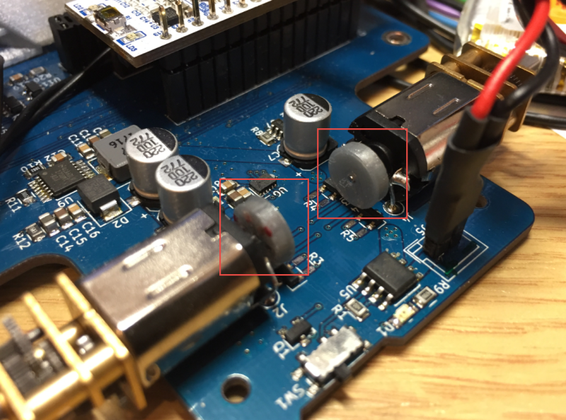
One of new bot’s features will be magnetic position encoders for the wheels. In the past, [Erich] has used the encoder disks that Pololu sells without issue. At 69¢ each, they don’t exactly break the bank, either. But shipping outside the US is prohibitively high, so he decided to try making his own disks with a 3D printer and the smallest neodymium magnets on Earth.
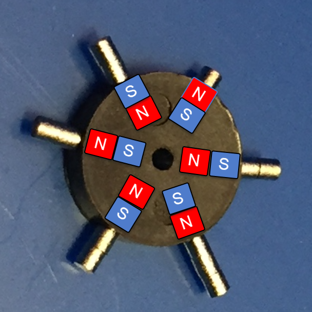
The pre-fab encoder disks don’t have individual magnets—they’re just a puck of magnetic slurry that gets its polarity on the assembly line. [Erich] reverse-engineered a disk and found the polarity using magnets (natch). Then got to work designing a replacement with cavities to hold six 1mm x 1mm x 1mm neodymium magnets and printed it out. After that, he just had to glue them in place, matching the polarity of the original disk. We love the ingenuity of this project, especially the pair of tweezers he printed to pick and place the magnets.
Rotary encoders are pretty common in robotics applications to detect and measure wheel movement. Don’t quite recall how they work? We’ll help you get those wheels turning.


Sumo bots competitions in Poland – same three guys reach podiums since 2010 while
suckersstudents with reasonably-priced bots waste their time and effort failing to move past qualifying stage. Similar story with line-follower competition.Wouldn’t the lowest cost option for a magnetic encoder just be a steel bar spinning between two coils? That would add pretty much no cost to anything on this.
Alternatively, I’m sure you could measure commutation noise in the motor reliably enough to track position, with little else than some filtering circuitry and a micro with an ADC.
Measuring commutation noise as a tool for motor position is an established technology. The major hurdle is trying to detect the commutation noise in the presence of a PWM motor drive. Modern digital filtering may be able to make some sense of it, but at least a few years ago it limited the applications to position-only off/on control type applications.
I personally first encountered it in automotive applications for HVAC blend door controls circa 1999. I doubt it was “cutting edge” then.
As to the “steel bar between coils”, sounds much like a “variable reluctance” sensor – which also works quite well for many applications (ABS wheel speed sensors for one). Primary weakness is that signal strength is proportional to speed, as such it’s not particularly suited for very low speed applications.
Depending on the rpm of the application, just send a reasonable high frequency current through one coil and watch the amplitude change on the other coil. Essentially coupling and uncoupling a transformer. Should be very easy to do with a micro and not resource intensive at all. And unless you go for precision and use it like a resolver, it’s a comparator away from a direct digital output.
very nice, make a product out of this please, cheap dc motor w/ gearbox and a small pcb on the side with this simple encoder. add an h-bridge or even full motor driver. if it is cheap enough it would be quite popular i think.
Or just buy a magnetic encoder IC like the AS5048…
SPI, I2C, PWM as output and super accurate, absolute position at astounding speeds…
Or just buy the robot pre-made…
I like to cut out the middle man and just order my own trophies.
No joke, resolver encoders are crazy accurate. They can be small too. Sometimes costly as hell, but you pay for accuracy.
Kristina Panos – One thing I just can’t understand with all rotary encoders, magnetic or not, is how does the decoding circuitry detect angular momentum DIRECTION? How does it know CW or CCW (aka anticlockwise)? Like how does the robot know it’s going forward or reverse? I know it’s something wicked simple, I just can’t see it yet…
You need two sensors shifted by π/2 (i.e. by 90 degrees, i.e. by half the way between a N and a S pole). That’s how mechanical mice used to do that:
https://en.wikipedia.org/wiki/Computer_mouse#Mechanical_mice
(see there for “quadrature signal).
“Quadrature” is the phrase that pays.
… perhaps even the “phase” that pays!
Ouch! :)
LOL’ng from the future in 2020 where there is a global pandemic and hoverboards still are wheel based
I’m no expert, but I think that typically there are two sensors which are spaced proportionally to the spacing of the encoder (similar to a vernier scale) so that in one direction they are closer to state change than the other. So that if there is a state change in sensor A before sensor B then it is rotating in direction A, vs. a state change in sensor B then sensor A it’s rotating in direction B.
Here is an explanation: https://www.edn.com/design/integrated-circuit-design/4363949/Decode-a-quadrature-encoder-in-software
The code in that article is kinda “meh”. It only decodes the quadrature on rising edges, which make it very succeptible to noise and half as accurate as it could be.
But see in the comments for the best (smallest, fastest?) code implementation I’ve ever seen:
http://www.mkesc.co.uk/ise.pdf (PDF)
Spoiler: uses a lookup table over the possible state transitions = no branching, constant time, as fast as a memory lookup. Elegant!
Interesting, I suspect that method has been independently “invented” many times. I happen to be using the exact same concept extended to three phases to do position tracking from the hall sensors in a BLDC.
For only two phases (typical quadrature encoder) a slight variation to that is (in my opinion) better. Use a single XOR from the present A phase to the prior value B phase. Add or subtract to the position counter depending on the outcome of the XOR.
The simplest way (a requirement for me) that I’ve found to decode a typical two bit gray code output is that the state of A when B changes state (or the state of B when A changes state) will tell you the direction the encoder is moving.
For a motor you often don’t need to, as you already know which way you’re driving the motor
This is forehead-smackingly true. Why the heck do you ever see quadrature encoders on DC motors then? (Seriously.) Detect whether you’re winning or losing in a near-stall situation?
And why the hell have I wasted my time on quadrature routines on small driven bots?
Thanks. I won’t be able to sleep tonight.
Because in automated motion control in such applications as legged robots where it’s important for the robot to know where it’s leg is at? Quadrature encoder rigs aren’t always used for speed sensing, but position sensing as well ya know
mikeselectricstuff – Yeah Mike this occurred to me after I posted. Like DUH! :-)
Thanks to everyone replying to this. I got it now.
the encoder produces an output which is asymetrical, music is asymetrical. if you listen to the stone roses there are two tracks in their only album which are the inverse of each other. one is played forward, the other is played back. listen to waterfall and don’t stop.
https://www.youtube.com/watch?v=zdpAECU34o4&list=PL3CFC62A6A79EF6BF&index=3
Wouldn’t an optical switch (or a retro sensor) with a slotted dish attached to the motor be cheaper (and reduce the total weight for a few grams)?
https://www.electronicproducts.com/images2/f32cherr0899.gif
>>reduce weight
>>Sumobots
And?
You put the weight where it matters, that magnetic disk also adds motor inertia, like a flywheel. You don’t want that.
What about potentiometer-style encoders? They would be a bit more expensive since you need two to account for the ‘dead zone’ (most have a usable range of ~300-330 degrees), but that’d still only cost around $2.50 in small quantities. Something like Murata P/N SV03A103AEA01R00.
Which, okay, isn’t great cost-wise. But it’s not bad and requires comparatively little overhead.
that’s great until the pot wipers grind a slot into the conductive track.
Always wondered why you can’t make an add-on for a servo with CR mod to use this so it still has some measure of proportional control. Wouldn’t need much, just a micro (eg PIC 10F222) or similar 6 pin with a V-F sensor similar to E-bike throttles or something similar. Not even a need to buy new parts as many cheap laptop and PC fans use similar sensors.