[Emilio Ficara] dropped us a line recently about his efforts to drag his television and receiver kicking and screaming into the modern era. His TV is old enough that it needs an external tuner, which means it requires two separate remotes to properly channel surf. He wanted to simplify the situation, and figured that while he was at it he might as well make the whole thing controllable over WiFi.
To begin the project, [Emilio] had to capture the IR signals from the two remotes he wanted to emulate. He put together a quick little IR receiver out of parts he had in the junk bin which would connect up to his computer’s microphone port. He then used an open source IR protocol analyzer to capture the codes and decode them into hex values.
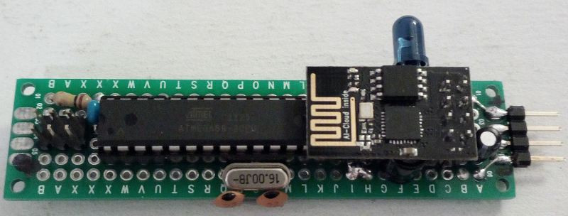
As a proof of concept he came up with a little device that combines an ESP-01 with an ATmega88. The ESP-01 runs a minimal web server that receives hex codes as URL query strings. These hex codes are then interpreted by the ATmega88 and sent out over the IR LED. [Emilio] notes that driving the IR LED directly off of the ATmega pin results in fairly low range of around one meter, but that’s good enough for his purposes. If you want to drive the IR LED with more power, you’ll need to add a transistor to do the switching.

Now that he can decode the signals from his original remotes and transmit them over WiFi via his bridge device, he has all the groundwork he needs to come up with a streamlined home entertainment controller. A native application for his smartphone or perhaps a minimal web interface is the last piece of the puzzle.
This project reminds us of a similar attempt at controlling legacy IR devices from a smartphone via Bluetooth. If you’re looking for more information about wrangling IR signals from your microcontroller, this primer from 2013 is still a great look at the subject.


Maybe I´m overlooking something, but couldn´t he drive the IR led directly from the ESP ?
My first thought exactly. Even with two gpio pins, driving the ir blaster should be fairly straight forward. Libraries for the atmega may be easier to work with. Now where to by a generic wifi remote… oh need to build that too.
the avr code is compatible with the esp. there is no need for a second microcontroller unless you need more inputs/outputs or more than one analog input.
I had the same thought. . . . and then I read the article.
It seems he was limited to parts on hand, and he’d already worked out some specific IR protocols using the AVR, which he used as the project’s base. This is a quick hack, not an optimized, manufacture-ready product. I’m sure he’d be fine with someone making an all-ESP version.
Overlooking just driving the data pin on the IR receiver directly.
I was sure I read something about the ESP8266 having a built in IR encoder/decoder, checked the datasheet and I was right.
Use a ESP12 or a Wemos D1 mini instead and you do not need an extra arduino.
While I like the minimalist approach, I have been using a wemos based board found on https://github.com/emc2cube/MySWeMosIRShield
Not using the nrf, or the smart home part as I have o use of it, just using the wifi, it’s pretty neat to control TV + sound system, and can add an IR receiver on it too to first capture the codes!
Super cool shield!
Reminds me of my remote control translator, but using a phone instead of another remote control to provide input.
As a quick and dirty solution parallel multiple pins to drive the IR led for more current, switching them simultaneous!
It’s a good idea. There is a problem for the timings, because I actually use the SBI I/O,#bit and CBI I/O,#bit instructions (Set or Clear I/O BIT). Both of them take 2 machine cycles to execute, while for contemporary output on multiple pins I must use the OUT I/O, R instruction that only takes 1 machine cycle,.. but I can repeat it 2 times, so no problem :) There is another problem with the OUT instruction: I must read the status of the port in a register prior to send the data stream and restore it at the end (other pins on the port must NOT be changed by IR procedure), but this isn’t difficult to achieve. At the moment, just ’cause the firmware is firmly closed (it was just a proof of concept) I will simply add a PNP transistor to get all the power I need. I will use a PNP ’cause the output is active low. Anyway, I appreciated your “quick and dirty” solution. Bye.
I’ve been using this approach: https://hackaday.com/2017/11/12/alexa-hack-my-tv/ and it’s been working fantastically.
Reinventing LIRC again again :/
How so? IIRC, LIRC allows your remote to control your computer, which is not what he is doing.
LIRC can also be configured as an IR Blaster. I used to use this so I could push power on my Hauppauge remote and LIRC would see the signal and then turn around and send the power signal to my tv from the IR blaster part.
esp01, $1,6
IR led, $0.05?
lirc… needs something like a rbpi (and a sdcard) and a IR led… a $10 minimum?
looks like reinvent is something good.
Im using remotsy, is a esp8266 ir blaster, it works with alexa or you can flash it with your own firmware, the guy has a source code and a python library.
https://www.tindie.com/products/jorgeci/remotsy-pcb-infrared-blaster/
One to rule them all. Logitech harmony. No more, no less.
15 bucks remote that can learn codes is cheaper solution for simple task like controlling TV receiver and TV. But yeah, Logitech Harmony is nice too.
If you are rich yes harmony is for you, I’m using remotsy, is more cheap and is the same that harmony or even better, search remotsy in google or get it in amazon.
If anyone needs the reverse (receive IR command and make a network request (in this case roku API)) https://github.com/lawrence-jeff/IRtoRokuBridge
> His TV is old enough that it needs an external tuner, ”
“…Just old enough…” and I could let it pass. My 1955 TV had a tuner as did some up to 2005 or 10. Then digital with better viewing came out… Better if you were less than 50 miles away instead of less than 70. Or if you could (& would) pony up a ridiiculous Mount of money for “cable.” I feel as if the author is 20 and with no sense of some of the readership having seen the moon landing. Sorry… it must be time fir my nap… or perhaps, yours.
I did something similar to make a Denon MD-31 MQTT-controllable. To keep things tidy I glued the IR led inside the case pointing directly at the receiver. There was enough space inside to tuck in an ESP8266 and buck converter powered from a 15V line.
http://ynformatics.com/wp-content/uploads/2018/01/IMG_9356.jpg
I laugh every time i see an ESP tied to the Arduino. You do know that the ESP can act just like an Arduino and is multiple times more powerful right? You can even code for the thing in the Arduino IDE and upload code from the Arduino IDE straight into the ESP. Just add the ESP to the IDE using the boards manager.
To those saying that it can be done from the esp, isn’t that above module just a WiFi-serial bridge, so lacks the gpio pins to get it done, and makes it a tonne harder to set up? This looks like a great “this is what I had” job, and a damn sight tidier than my attempts. (I assume that from the dip atmega8, who buys those now with cheap nano / micro clones, or even bluepill / esp boards)
Awesome project g
The ESP8266 has far more IO than an Arduino. The particular ESP module he is using does only have 2GPIO pins available. Look up the nodemcu for a better ESP8266 module that brings out all of the IO pins.
Even in the case of his project, it is only needing a single GPIO for the IR LED. The module he is using could do it.
As for using the ESP for other uses than its default wifi bridge mode. All you gotta do is hook up its serial to a USB to serial adapter, load up the arduino IDE, select the ESP8266 board in the boards manager and then program away just like you would an arduino.
Have done the same …german, maybe you are happy with this or tranlate .. maybe it helps someone
http://www.henning-mersch.de/projects/wlan-fernbedienung
Effective.