The BBC micro:bit single board ARM computer aimed at education does not feature as often as many of its competitors in these pages. It’s not the cheapest of boards, and interfacing to it in all but the most basic of ways calls for a slightly esoteric edge connector. We’re then very pleased to see that edge connector turned from a liability into a feature by [Fabien Chouteau] with his handheld console, he uses micro:bits preprogrammed with different games in the manner of game cartridges in commercial consoles.
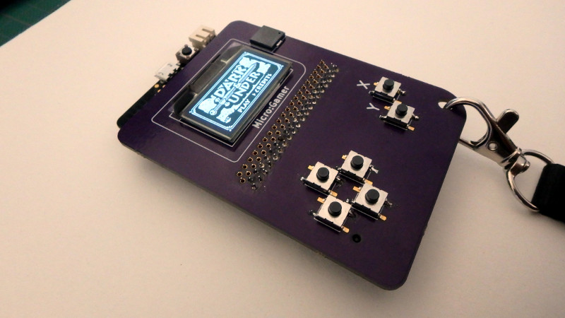
The micro:bit sits in its edge connector on the underside of a handheld PCB above a pair of AAA batteries, while on the other side are an OLED display and the usual set of pushbuttons. It’s a particularly simple board as the micro:bit contains all the circuitry required to support its peripherals.
He’s coded the games using the Arduino IDE with a modified version of the Arduboy2 library that allows him to easily port Arduboy games written for Arduino hardware. It’s a work in progress as there are a few more features to incorporate, but the idea of using micro:bits as cartridges is rather special. There is a video of the console in action, which we’ve placed below the break.
If the micro:bit piques your interest, you might like to take a read about its software stack, and have a look at our review.


I was just going to comment on this being a modern recapitulation of the Microvision from forever ago, and then I got excited by the LEDs on the back of the micro:bit.
Now I’m trying to figure out how you’d make an interesting dual-screen game where the screens can’t easily be seen at the same time.
Yeah, pretty similar concept. Microvision had its display, controls and power supply in the base unit. Each cartridge had its own CPU and game program code plus integrated overlays for the 12 button keypad. The base unit also had a small paddle controller knob.
So what this needs is a larger screen (can the micro bit do color?) and more buttons. The LEDs could be used by having a set of light pipes in a molded case. Bring those out to the front, around the edges of the larger screen. On screen indicators could relabel the lights, or the lights could be blinked to indicate things like there’s a monster to the left in the maze.
The Micro Bit’s LEDs are just red. It could manage a colour screen of course if you fitted one.
I think 360 degrees is asking a lot from light pipes. It’d be 90 for the first turn, 180 around the edge, and 90 more to face the user. It’d be much more practical to add LEDs to Fabien’s design if he wanted them, and there’s no real need. A bright kid could come up with some use for both screens if he wanted to, I’m sure. As long as the Microgamer doesn’t interfere with their pins, but I imagine it doesn’t. Actually if I were designing the Microbit I wouldn’t bring the LED driving pins out to the connector. Maybe it doesn’t.
The same bright kid might come up with some physical thing to add to the front LEDs. If not light pipes, something else, part of the challenge.
Documentation says that the LEDs are electrically a 9×3 matrix, and the six of the nine columns are also brought out onto the card edge.
Default firmware apparently also can use them as a light sensor by taking advantage of LEDs being lousy photodiodes. Might be a more obvious way for games to use them…
Quite impressive to use them for input. You could press one up against the other for data transmission, sending your Pokemon or whatever between cards. Kids might like that. The LED as photodiode thing is usually just a curiosity, unusual of them to build it into the firmware.
I think there was a story on here a while ago about some circuit, maybe RAM, that was kept powered for years and years through sunlight shining on it’s power-on indicator LED. Took ages for whoever it was to figure that out.
“can the micro bit do color?”
In theory you can but this monochrome display is already taking 1k of the 16k of RAM. And RGB display would use all or almost all the RAM for the frame buffer.
You could use a tile-mapped system to save on RAM, since the display would have it’s own buffer, and sprites. Or a custom kernel. I like it as it is though, it’s cute and looks more easy to manage.
I guess you are right, there are solutions I could to have an RGB display. Maybe for version 2 :)
Make a multiplayer game where only the other people can see some information about you..
That is a great idea!
I like the idea, even the execution, just that I’m not into games (much). That “overshoe”, (aren’t all boards that connect to microprocessor boards named after something that is worn, e.g. hats, capes, shields…) could also be the basis for test equipment, e.g. oscilloscopes, function generators, data loggers…
But since gaming is the “push” for more capable PC’s, this may be the best way to get more kids into the micro:bit.
If you’re doing a scope, etc, you’re probably best using some other board. The Micro Bit is aimed at kids, and games is absolutely the best way to get them interested.
Awesome – those SSD1306 OLED displays are amazing.
So, they got away with only 6 capacitors and 1 resistor to drive it? I guess that the Micro:Bit probably has I2C pullups and a voltage regulator, and they omitted the RCD filter which most ebay modules put on the reset pin?
So does that mean the resistor is current reference, and the capacitors are just the ones for the supply and charge pump pins?
Nice work. I don’t know much about the micro:bit but there is surely a SPI peripheral to connect an SD card. If there is enough RAM storing games on SD card and loading them in RAM for execution would be more interesting than switching micro:bit card.
Thank you!
There’s indeed an SPI controller on the micro:bit (nRF51). I’m not sure how we would be able to load games from the SD card because there’s only 16k or RAM, that’s not a lot for code + data.
Nice, but really crying out for audio.
It either has, or he’s working on adding, a buzzer.
Yes, the buzzer is already on the board but I still have to write the driver.
That game looks neat, anyone got any idea what it is?
Dark & Under? For the Arduboy?
Yes its Dark & Under .. you can find it here > https://github.com/Garage-Collective/Dark-And-Under
There is also a level editor so you can make your own here > https://github.com/Garage-Collective/Dark-And-Under-Level-Editor
Should have added, there are hundreds of games here > http://arduboy.ried.cl/
And the Arduboy definitely has sound!
Nice platform. I am one of the authors of the game you use in your demo. I love that it is being used on platforms other than the original Arduboy.
Thank you! Which game is it? I started to port those 3 because I think they are really impressive given the limited resources available.
Its called Dark and Under ..
As mentioned earlier you can find it here > https://github.com/Garage-Collective/Dark-And-Under
There is also a level editor so you can make your own here > https://github.com/Garage-Collective/Dark-And-Under-Level-Editor