We’ve said it a million times before: 3D printing will expand your horizons. The more you print, the more you think about things you could print and new ways to use printing in the process of building projects. [AHNT] knows all about this phenomenon, because he thought of a way to use soda cans as canvases for customizable pixel art lamp shades.
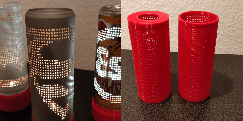
[AHNT] designed a printable sleeve that fits perfectly over 250mL cans. It provides a sturdy grid for poking tiny holes with a medical needle, and can be reused indefinitely with any pattern imaginable. He created two different printable bases to illuminate the lamp: one is sized to hold a votive candle, and the other is made for an LED strip circuit with a rocker switch and 12 VDC barrel jack. We suppose it wouldn’t take much to use an RGB LED instead—a Trinket or a Gemma would surely fit in the base.
In the video after the break, [AHNT] talks about prepping the can by cleanly removing the lid, which he does by filing the top edge until the layers separate. He also discusses a few methods for removing the paint, and notes that sandblasting worked the best.
Don’t need another lamp? There’s a million things you can do with that empty soda can. You could make a theremin, or a battery, or even a treasure box. Cut it open and make a solder stencil. Or do something else entirely, and send us a tip.


Did this with AL foil and a 3D printed star map. One gutted 200 lumen flashlight later, projected star map.
Who is this AL and why is he a foil? :)
Because Al is everything Plaite Steele isn’t.
https://www.youtube.com/watch?v=uq-gYOrU8bA
Oh, great. I got Al rolled
Dang, this guy really has the retraction settings dialed in.
It’s like he stuck a needle in every hole or something. :)
But, you are right. That is a print you’ll need a dialed in printer for even if it was printed really slowly.
retraction is the slowest part of my 3d printing on a delta, this must have taken forever. Print, retract 6mm, load 5.5mm, move, print, retract 6mm… still going in the morning?
If you’ve got a fast delta, try turning your rapids up as high as they go and then just turn retraction off. I run like this at ~400mm/sec rapids with good results.
Thanks for the suggestion, I will give it a try. I doubt i can hit 400mm/s as i am running a ramps board and tmc2100 that don’t take a lot of abuse. 120mm/s is what i currently run but it will leave strings if i don’t retract some.
Some hams made vertical antennae out of beer cans soldered into towering accomplishments to propagation, RF that is. 40 meter vertical made over time, that’s quarter wave!
https://hackaday.com/2018/01/26/drink-lots-of-beer-to-raise-your-monopole/
Neat idea. But I’d skip the 3D printer and try and do some more specific CNC based hack, such as mounting the can on a threaded bar and having the needle on a solenoid so that it can punch the can with a lot more, smaller holes as it travels a spiral path relative to the can. Except it is the can that is rotating and moving on one axis as the threaded rod moves through a mount point, the needle just moves in and out. I wonder if part of a sewing machine could be used for such a hack so that it was fast and strong enough. Then you can write some software to hole-punch any 1 bit image into a can. Using a drill could work too, but be a lot slower, however it would expand the range of materials your “cans” could be made from and adjusting for can size is possible too.
That sounds awesome!
Now go do it.
Cut a bunch of rings of rubber (stop at a tire shop and ask for an old failed inner tube to use as material, or get a damaged wetsuit from a dive shop) and make an expanding plug – pass a long bolt through the middle of a stack of rings, with large ‘fender’ washers (or wood discs) at either end, and cap with a nut. The bolt should be at least a couple inches longer than the interior of the can, and the stack of washers in a snug but not yet compressed state should probably be an inch or so longer than the can. Insert into can, and tighten the exposed nut – as you do so, the compression causes the rings of rubber to expand their OD, securely grabbing the interior of the can. This of course is only really viable if the top neck of the can (where it bends inward) is removed. The exposed end of the bolt could be used for securely mounting the can to a stand or into a CNC to rotate the can.
A quicker, lower tech approach would be to get/make a large dowel (a block of wood turned on a lathe to get just the right diameter as you’re unlikely to find one the right size at a homecentre), with a wrap of rubber (see above), would help keep the can from deforming as you punctured it. When done, extract the dowel first, then fold the rubber inward and extract (due to the flared bits of metal from the punctures, that is likely to keep it from just being slid out with the dowel).
An approach which would be less fiddly, but likely more work to source parts for would be two parallel rods with rubber rollers (envision paper feed rollers in an older printer or typewriter). The outer roller could be attached to a drive mechanism with a stepper, or even a handwheel that allows you to rotate it in a consistent manner.
The 3D printed mesh doesn’t address how you establish your pattern (unless you’re printing a separate mesh for each pattern, which sounds like a painful exercise on the 3D printer). Seems like it would be trivial to use an illustration or graphics program to make up border templates for different size cans, and import and scale images in there, pixelizing them in software and then printing, or just printing the borders and drawing your pattern. Cut to the size of the the border and tape that to the can exterior, wrapping it around and taping when it completes the circuit around the can. A simple apparatus like a small “tee square” which you could 3D print or make from wood or metal (or my preference – laser cut acrylic) could provide you with 2 or 3 rows of holes at your desired spacing over the face of the can and be square across the can face. If you’re using an expanding plug or a dowel as I mention above, the punching template could be fitted to a bolt in the middle of that, keeping it in registration, and the other side, I’d be prone to mount to something that rides the dimple at the base of the can. Pop a row or two of your holes (lengthwise along the can), then rotate the fixture so that the prior set of holes lines up in the unused row in the punching template, then punch your next row(s) of the pattern. Large regions of empty space would be more difficult to keep spacing on, but if your printed template has say small dots in the empty space, and larger ones in the spots to be punched, that would be sufficient for alignment. The print template could also be made to have a grid on it for aligning the punching template.
The punch tool could be made from different diameter nails or drill bits set through a wooden dowel with a specific length exposed – allowing for a consistent hole diameter because each press through the punching template bottoms out against the end of the wooden dowel.
3D printing enthusiast with Piercing Ideas.
If I remember, this isn’t a new thing, but the use of the pin guide is handy.
Should look up those shakey candle flicker lamps. Came from the same time period as this fad.
Put the can in a rotating holder, have an axially moving tungsten or graphite needle and a good power source. Then zap the holes CNC controlled.
You probably need some kind of xenon-lamp ignition transformer or a beefed up version of a gas discharge lamp PSU. By controlling the charge of the capacitor it could be possible to control the size of the holes.
Add a dielectric and you’ve just invented an EDM lathe.
Wonder if the can could be cut by laser, the material is very thin. There was a kids game in the early 80s that used a similar idea, but was based on transparency film with a preprinted grid which could be coloured in with sharpies. The cylindrical design was then rotated on a backlight thingy. Pretty effective.