We’ve become used to software-defined radio as the future of radio experimentation, and many of us will have some form of SDR hardware. From the $10 RTL USB sticks through to all-singing, all-dancing models at eye-watering prices, there is an SDR for everyone.
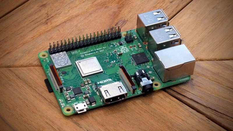
What about the idea of an SDR without any external hardware? Instead of plugging something into your Raspberry Pi, how about using the Pi itself, unmodified? That’s just what the Nexmon SDR project has achieved, and this has been made possible through clever use of the on-board Broadcom 802.11ac WiFi chip. The result is a TX-capable SDR, albeit one only capable of operating within the 2.4 GHz and 5 GHz spectrum used by WiFi.
The team had previously worked extensively with the chipset in the Nexus 5 phone, and the SDR extension was first available on that platform. Then along came the Raspberry Pi 3 B+ with a similar-enough WiFi chipset that the same hack was portable to that platform, et voilá: WiFi SDR on a Pi 3 B+.
If you’ve not looked at the Pi 3 B+ we’d like to direct you to our review. If you don’t have a Nexus 5 kicking around, and you’d like to do some WiFi-band SDR work, it’s looking like an amazing deal.
Via rtl-sdr.com.


Getting raw I/Q access on low cost commodity chips is the holy grail in terms of hobbyist sdr.
RTL-SDR is the best known example of it.
This has some serious potential for making low cost wide band SDR transceivers even more available.
“only capable of operating within the 2.4 GHz and 5 GHz spectrum used by WiFi”
That is not “wide band SDR”
ad external mixer and voila
Right, that’s what I was thinking. What is the bandwidth on these? Is the chip MIMO-OFDM?
Reads like from wikipedia that there is potential for 160MHz bandwidth and at the very least 6-8 if not more likely at least 20MHz
https://en.wikipedia.org/wiki/IEEE_802.11
A mixer capable of working at 2.4GHz is not a thing anyone can solder. To receive much lower frequencies, say the HF, one should also build a local oscillator working near 2.4GHz which would drift like crazy.
Is that because the traces need to be critically measured and tuned… maybe even solder blobs spec’d out critically? Can the 2.4 and 5.8 be mixed and filtered to provide even broader range? I’m guessing some sort of relay circuit would be needed also.
Im sure Minicircuits has something suitable in stock.
id say attaching a purchased board via soldering may be possible, doesnt one of the pi models have an unpopulated ipx antenna pad?
Digikey just mailed me a brochure that notes an Analog Devices LTC5553 and maybe use that with a LTC5594. That system would have to be hacked into for use though would make a wide band SDR system if you can make the PCB board. The evaluation boards however are outrageous in price compared to the chips… or at least on my budget.
Wideband as in tons of MSPS. RTL-SDR is only 2.4MHz wide, compared to 61.44MHz wide for LimeSDR.
Or 48kHz/192kHz for common soundcard transceivers.
I could have been clearer.
Adding a HackRF style converter in front of it would fix that.
And that is something that might get done if something similar is doable with USB versions.
SDIO and other weirder embedded stuff is a bit meh for making a general purpose SDR.
I reply to you and the other comment I’d like to point out that you can’t compare bandwidth from one end of the spectrum to another and use the same unit, that is MHz, obviously a megahertz at 27MHz for example is much wider than a MHz at 5 GHz in percentage. And if you go shortwave it would become even more illustrative.
Does anyone have block diagrams of the processes and also for the open source analyzers?
https://www.vistumbler.net/
https://github.com/libremesh/spectrum-analyzer-packages
https://github.com/VREMSoftwareDevelopment/WiFiAnalyzer
I’m wondering where the gaps are in making a more interactive SDR interface to visualize transmission, transmit and not only receive.
Might be right in my face obvious and I am overthinking.
I still haven’t hacked a router with OpenWRT yet or really even coded any communications applications. This is on my to do list and am wondering what is already opensource that can provide leads into the transmission processes and then modify those processes for communications in areas where there are free channel regions available to use… or even just outside those regions for use.
Might be easier for the opensource communities to be able to visualize where the gaps are faster so to jump into the code or where to sniff out more if not deobfuscate on the market software to see the format of the code using block diagrams or a flow chart basically.
Be nice to see what cellular can do.
Yeah. Too bad that the DSP cores used there are usually behind rather extensive NDA’s.
Same for all hardware documentation.
I was just a few days ago looking into the more cost effective systems and their chips for the audio I/O interfaces like the highest SNR Creative Labs XFi Titatium HD card that is 122dB though looks like they use a PCM1794A which has a SNR or Dynamic Range of 132dB. The input sampling has some latency and is only 96kHz which seems can be 192kHz with the chip.
I’m just now getting into the boards more and details of the circuits and chips comprehension and visualization in my mind… so seems I need to read up more on the signal qualities of the higher frequency chips since with mixing and filtering and VCO’s there are some interesting way more cost effective potential applications for SDR use with ultra low noise or low noise components and design (grounding & shielding) to lower the noise floor, increase the dynamic range and explore a high bandwidth.
I’m still in the 90’s with the science, tech and engineering though. I feel like I’m in the 1700’s with my maths. :-|)
You might find guidelines for achieving TEMPEST compliance useful.
I really do need to study those. I never was signed off on training since never needed to be trained on though have been aware of for half my life seems… ew… yeah… literally with an age reality check. I’m catching up on the range of higher level laws first before getting back into detailed regulations, protocols and standards. The Ten Commandments just isn’t cutting it now days. Get’s more trickier without knowing the lingo of the legal looking robbers.
Wow, the wikipedia article is really updated: https://en.wikipedia.org/wiki/Tempest_(codename)
Great to cursory review and see… I’ll read into more details. Advocating cyber crimes issues was one thing… now seeing the wireless need for advocacy is even more concerning since living systems are being hacked into or really forensically clean hacked to death.
so, this means the Pi could talk Zigbee i assume…
This would be useful. Plus z wave
YAY! Pi femtocells here I come!
Channel select-able? If so, this is a cheap solution to a question about 2.4Ghz propagation beacons my ham radio group was asked a few years ago….
“Channel” is just an offset from the declared frequency
Yeah, depends what protocol you’re using I’m thinking. The 802.11 channels are pretty much just standardized frequency ranges. https://en.wikipedia.org/wiki/List_of_WLAN_channels
I have to read more into how the SDR application interface is working, like has anyone integrated with a GUI like GNU Radio, HDSDR or SDR# or reads like only command line operations and maybe a seemoo application???
Crap, I just noticed I missed the rtl-sdr.com link. I don’t have a pi… though rpitx looks like the app I was wondering about.
Maybe I can read my ComEd SmartMeter over Zigbee directly? Would be sooo nice.
Mysensors protocol would be nice.
Can this run on PI Zero W?
No as an 802.11ac Wi-Fi chip is required.
In case you want to learn more about Nexmon, I recently published my PhD thesis about this topic. Feel free to download and read it: http://nexmon.org/thesis
Remarkable
An absolute joy to read! .. (love the little summaries too).
Your doctorate was well earned; this is excellent research, well written-up. I won’t go on further, because no words could do it justice.
I look forward to seeing all that comes of this “NexMon” project.
Again, well done.
2.4 GHz is quite simple. I had some success recycling the DRO from security alarms, at least to some extent.
Also relevant (or was that resonant) the PCB is very simple. If you want to set it up as a local oscillator just run it at low power with a regulator inline with it. If anything the problem is you can’t tune these.
For some applications its also possible to use the 2nd harmonic on a Sky LNB (eg SETI) as these are quite cheap now.