Even when you build something really, really nice, there’s always room for improvement, right? As it turns out for this attempted upgrade to a DIY spot welder, not so much.
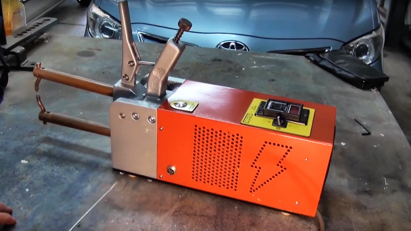
You’ll no doubt recall [Mark Presling]’s remarkably polished and professional spot welder build that we featured some time ago. It’s a beauty, with a lot of thought and effort put into not only the fit and finish but the function as well. Still, [Mark] was not satisfied; he felt that the welder was a little underpowered, and the rewound microwave oven transformer was too noisy. Taking inspiration from an old industrial spot welder, he decided to rebuild the transformer by swapping the double loop of battery cable typically used as a secondary with a single loop of thick copper stock. Lacking the proper sized bar, though, he laminated multiple thin copper sheets together before forming the loop. On paper, the new secondary’s higher cross-sectional area should carry more current, but in practice, he saw no difference in the weld current or his results. It wasn’t all bad news, though — the welder is nearly silent now, and the replaced secondary windings were probably a safety issue anyway, since the cable insulation had started to melt.
Given [Mark]’s obvious attention to detail, we have no doubt he’ll be tackling this again, and that he’ll eventually solve the problem. What suggestions would you make? Where did the upgrade go wrong? Was it the use of a laminated secondary rather than solid bar stock? Or perhaps this is the best this MOT can do? Sound off in the comments section.


The secondary will have less resistance, definetly, also disipate heat more quickly, but withour a way to measure the output curretn, he cannot know if the efficiency improve or not.
Did he beef up the primary? Maybe it wasn’t the secondary that was the limiting factor…
Primary’s probably the limit.
He just drop voltage to half by taking one round away. So probably voltage is now too low or that secondary is now too thin so that it make too much voltage drop for that higher current. Looks that there is still quite lot of room to put more copper plates for that secondary.
Yes, that’s the problem. His secondary voltage is now lower, so he ends up with less current.
Not really, he is going into a dead short, output current will be twice what it was but voltage half = same delivered power.
Power is not the problem here.
A true short would imply zero voltage (ignoring the wire inductance), so the power can’t possibly be the same. The power lost in the secondary winding doesn’t really matter, it’s the current through the workpiece that counts; he said he didn’t see an improvement, if the current doubled, he would have noticed!
It’s not a superconductor. The voltage will never be zero. The entire secondary winding acts like a resistor.
He was already saturating the transformer core with the original winding so it is not going to draw any more current in short circuit, He needs a bigger core. Figure a 1200w microwave and he was pulling 6ish amps, thats about right for 230v mains.
You can get the approximate capacity of a transformer by measuring the core and using this equation core area(sq in) = sqrt(60/f)*sqrt(wattage)/5.58 f is line freq,
He should have twice the current out of the tongs but half the voltage so maybe 1v vs 2? Still the same amount of power being delivered.
Was typing my thought if same when you posted this…. great minds think alike! ;)
His secondary voltage is too low to overcome ohmic losses in his secondary circuit.
I doubt it. Most spot welders run around 1v OCV.
He is lucky to be getting 0.25V here. Is coupling loss is high, and he has less than one full turn. His primary current is lower after adding the strap.
Would you mind clarifying what you mean by “coupling loss” in this context? I’m fairly sure that’s something you just made up, unless you mean leakage inductance, but I fail to see why that would be particularly high on the case, assuming the magnetic shunts were removed.
This IS a full turn, for all practical purposes, since the magnetic field is almost completely constrained to the iron core. Also, it is mathematically impossibly to make 3/4 of a turn while still having a closed circuit. It doesn’t matter how far the last bit of wire is from the core, the magnetic flux still has to go through the loop.
Yes, leakage inductance. If the conductor exits the magnetic field, you end up with less than one full turn, and less than the voltage produced by a full turn.
The OCV on my spot welder runs 2.8V, but it’s secondary is optimized for lowest possible resistance.
@Sparkygsx- A transformer of this design would not use shunts, unless he was trying to build a current limiting transformer, but that is not the goal here. Also, look up “coupling loss” and coupling “efficiency” in transformers to learn more about the subject.
Could also be a factor of magnetic core saturation. Can think of several examples where core saturation is purposefully used for regulation; in Stabline constant voltage transformers and in the power supplies used in Sony CRT type TVs. Sony used a DC swamping coil to saturate core for the purpose of regulation. (Also making them the ONLY switch supply I ever encountered where switch frequency would increase when desired voltage was obtained, rather than decreasing.)
Secondary current reduces core saturation instead of increasing it; the core is most heavily saturated with zero secondary current. I can’t tell for sure if the magnetic shunts are still in the core, but it looks like they have been removed, otherwise they would certainty be limiting the current.
I doesn’t work that way. The field intensity in the core is a function of primary current. Zero secondary current can push the flux intensity closer to saturation (due to hysteresis losses) for a given core material and construction, but because back EMF cannot increase the field intensity (because you are not adding energy to the system), it generally has little effect on saturation. There are special transformer designs that use an additional winding to push the core into saturation for special applications though.
Incorrect. The magnetic flux density is directly related to the primary current. Higher secondary current = higher primary current.
Until saturation….
old one was loud because wire vibrated like crazy :0 wonder if dipping secondary wire in epoxy(high temp resistant variant just to be on a safe side) wouldnt make it silent
It’s quieter and consumes less amps on the primary because it’s outputting less power..
Pretty sure replacing that wire took it from roughly 1.75 turns down to about 0.6 of a turn, just think about how much of the wire is actually hit by the magnetic flux. Now that lower voltage generated has to combat very similar wire losses compared to the cross section of the previous wire used.
Ohms law still holds very true, you want enough voltage to overcome Ohmic losses and deliver maximum power to a load that pulses hundreds of amps, so you have to model that, but also have a good grasp on realistic wire resistance.
But at the same time you also don’t want it to arc excessively or use such thin wire that those losses drop the voltage to zero.
In my current spot welder prototype I calculated I could get a bit more power out of it, if I dropped down a wire guage and added another winding, BUT it also was going to significantly increase the power dissipation of the windings themselves and would have given me lots more heating.
You win an internet cigar!
He could’ve used a thicker lamination. Looks like he had plenty of room in there for about twice as much copper. Not that it would’ve made a significant difference.
For all the ‘saturation’ comments above.. Magnetic core saturation is NOT a function of primary or secondary current in this transformer configuration. It follows Faradays law. The Applied primary voltage, the cross sectional area of the steel core, the number of primary turns and the operating frequency determine the magnetic flux density. Nothing else, in this case.
The power loss is due to ohmic effect of the primary wire and the secondary wire resistances and The primary to secondary coupling quality (leakage inductance).
Not to enter into the fray of electrical discussion but looking at the build one thing comes immediately to mind – the actual contact points (electrodes).
I tried a prototype some years ago and while I measured in the region of about 900 Amps at somewhere around 1.4 volts using 1 full turn of some 75mm² copper cable I had going spare , I got piss poor results! For what I needed to do anyway!
My biggest stumbling block I concluded as I remember was copper electrode contact points.
I did’nt have anything even close to the conductor I was using , to deliver full available current where it’s needed – at point of contact!
It seems obvious to me that – for my own account anyway – the reduction of current carrying capacity in the electrodes to be able to deliver the 900 odd amperes that I was reading under loadv, caused by the smaller size of the contact points meant that not sufficient heat was able to saturate the weld puddle to fully fuse the metal. Stainless steel (316L in this case) being a poor conductor of heat in general.
It was my intent to get some electrodes suitably matched to the 75mm² but as things will , life got in the way and the build is still in the WIP box.
Having said all this , my aim was to weld 0.8 -1.2 mm stainless for another project – the reason for wanting to spot weld was to get a nice aesthetically pleasing and at the same time solid joint – Tig welding would be acceptable IF I did’nt have the problem of lack of steady hand control probably due to ageing and muscular degeneration.