[Angus Deveson] published a video on “solids of constant width” nearly a year ago. Following the release of the video, he had a deluge of requests asking if he could make a bearing from them. Since then, he’s tried a number of different approaches – none of which have worked. Until now…
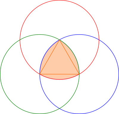
What is a solid of constant width? A shape whose diameter is the same in all orientations, despite the fact that they aren’t circular. In particular, the Reuleaux Triangle is of interest; if you’ve heard of square drill bits, a Reuleaux Triangle is probably at play. Constructed from three circles, they make a neat geometrical study. When placed between two surfaces and rolled, the surfaces will stay parallel, despite the fact that the center of the triangle does not stay level.
In theory, this means they could be easily substituted for spheres in a classic roller bearing, but this turned out to be problematic – the first attempt determined how hard it was to get the shapes to roll instead of slide.
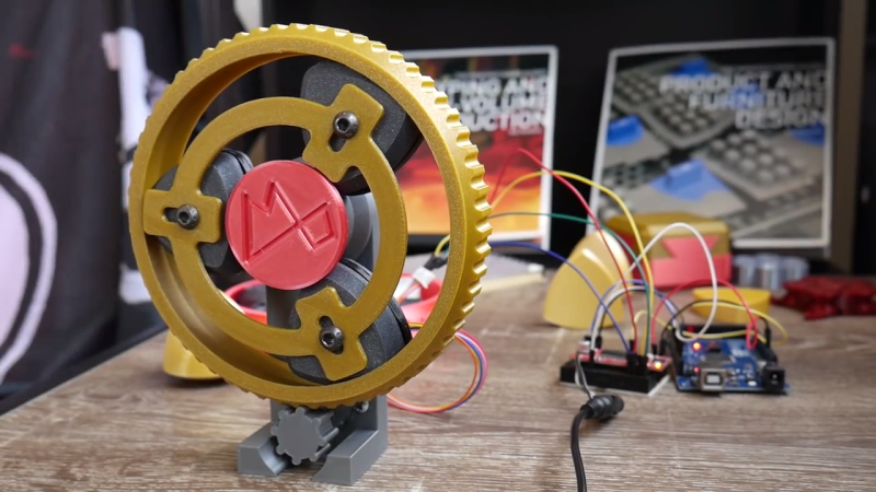
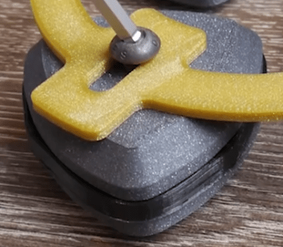 [Angus] finally arrived at a working bearing after a ton of suggestions from the community, and trying a number of attempts until he was able to achieve what he set out to do. The trick was to create a flexible insert (3D printed as well) for the center of the triangle edge, which grips the surfaces the triangle comes into contact with. A frame is also made to hold the bearings in place and allows their centers to move up and down as necessary.
If the thrill seeker within you still isn’t satisfied, maybe you should try the Reuleaux Coaster…


My very first thought was, that looks like the piston in a Wankel engine.https://en.wikipedia.org/wiki/Wankel_engine#Design
After watching the video, it is not, but it is similar.
Piston? You mean rotor?
I think of anything that compresses a fluid by reducing its volume as a piston. Technically piston does fits the dictionary definition “a disc or short cylinder fitting closely within a tube in which it moves up and down against a liquid or gas, used in an internal combustion engine to derive motion, or in a pump to impart motion”
Fidget Spinner 2.0 (:-D)-}–{
The interesting bit is the movement of the centers relative to one another, and whether that could be used for any effect.
I was thinking along these lines too. Attach a rod in the direction of motion to the centers and you get a reciprocating motion. If those centers can be timed in the right way, you might be able to drive a crank in the center if the device.
Could it transmit a usable force?
What is the relationship of input force to output force?
What sort of backlash is there?
I’m willing to bet someone has studied all this and it’s in an old, obscure book of mechanisms somewhere.
cool!
The logic should follow that the slots in the carrier should be squares, not?
this is very cool indeed. I’m not a mechanical engineer so i just wonder if this was done just for fun or if there is actually a practical application for such a bearing?
This is just for fun. It has no practical advantage whatsoever, apart from probably being a great conversation piece.
If he wanted to give it more functionality he could make make it into a clock.
Attach a glass plate to the bearing cage and mount the hand mechanism in the middle and it could become something like a Jefferson Mystery Clock.
It would work much better if the radius at the corners would be closer to the radius of the sides ;)
But then you would need some kind of polygon with an infinite number of sides for it to roll smoothly.
Well, it seems it makes a line contact instead of a point contact, so it could be better than ball bearings; though, a cylindrical bearing also offers a line contact.
I once heard from a professor about a time he’d been asked to help out a major bowling ball factory where their QC testing left something to be desired. They had been accidentally making Reuleaux triangle bowling balls and weren’t catching them in QC.
There was a great science fiction novella by Poul Anderson that was based on this sort of geometry. It’s called “The Three Cornered Wheel”. Worth looking up.
As a UK dweller we have coins this shape :)
Everyone is familiar with the concept.
I wonder if there is a way to use the triangle center offset for something like a strain wave gearing or the abacus drive.
I wonder if the inserts ‘migrate’ in the opposite direction of rotation with respect to the bearings like the flexspline does on strain wave gearing assemblies.
Chart patterns such as “Triangles, Flags and Wedges” are price formations that will provide you with consistent profits.
Before the age of computing power, the professionals used to analyze every single chart to search for chart patterns. This kind of analysis was very time consuming, but it was worth it. Now it’s time to use powerful dedicated computers that will do the job for you:
==> http://www.forextrendy.com?kdhfhs93874
Stupid question: what is /are a reuleaux??
While the constant width allows for smooth rolling, it creates difficulties in keeping the center stable. The author describes how Angus Deveson finally achieved a working bearing by adding a 3D printed flexible insert to the triangle’s edge and a frame to accommodate the up and down movement of the center. You can check more at https://en.tradebearings.com/list_22.html