Slicer Settings For “Indestructible” Battle-Bot Worthy PLA Parts

If you follow [Maker’s Muse] on YouTube, you know he’s as passionate about robot fights these days as he is about the tools he uses to make the robots. Luckily for us, he’s still got fame as a 3D printing YouTuber, as this has given him the platform to share his trade secrets for strong, robot-combat-worthy prints.

He fights robots in a ‘plastic ant-weight’ division, which restricts not only the weight of the robot but also the materials used. Not only must they be primarily plastic, but only certain plastics are allowed: PLA is in, but engineering filaments, Nylon, and TPU are out. Since necessity is the mother of invention, this has led to strong evolutionary pressure to figure out how to print the most impact-resilient PLA parts for armor and spinners.

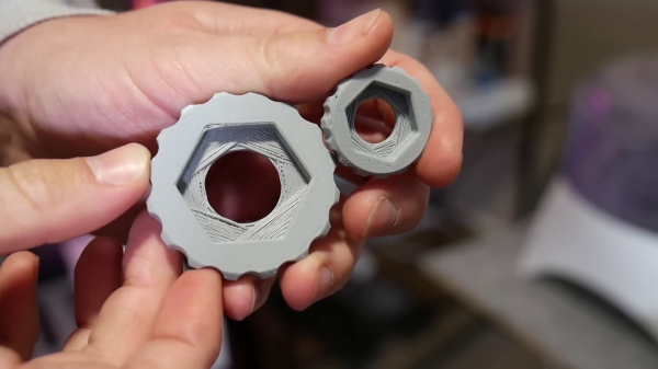
He’s using the latest OrcaSlicer and shares the profile as a pay-what-you-want 3MF file. It’s all about solidity: a solid part with solidly fused walls and solidly linked layers. It makes sense: if you’re going to be hammering on or with these parts, you don’t want any internal voids that could either collapse or pull open.

The infill density is obviously 100%, and you’ll want a concentric pattern — this makes it look like you’re just printing walls, but it allows you to use another trick. To make sure those walls don’t all align, creating a potential weakness, OrcaSlicer’s “alternate extra wall” will put one extra wall every second layer. The extra wall causes the infill pattern to stagger and lock together.

Also helping lock it together, he’s playing with extrusion widths, with the suggested rule-of-thumb being the line width on the walls be one-half that of the internal fill — and as wide as possible. In his case, with a 0.4 mm nozzle, that means 0.4 mm wide walls and 0.8 mm for the infill. OrcaSlicer 2.3.2 also lets you play with specific flow ratios, allowing you to overextrude only the internals for strength, without overextruding on the walls and potentially ruining dimensional accuracy. He also irons all top surfaces, but admits that that’s mostly about aesthetics. The iron may make those layers a little bit stronger, though, so why not?

Would brick layers make these parts even stronger? That’s very likely; [Maker’s Muse] mentions them in the video but does not use them because they’re not implemented in-slicer, and he wants something accessible to all. On the other hand, this post-processing script seems accessible enough for our crowd.

This video/profile is exclusively about fully-solid parts. When you want strong parts that aren’t fully solid, it looks like the answer is walls.

, Continue reading “Slicer Settings For “Indestructible” Battle-Bot Worthy PLA Parts”

3D Printing Bores Without Support

If you’ve done even a small amount of 3D printing, you probably ran into the challenge of printing a small hole on top of a larger hole. The conventional solution is just to add support, but in the video after the break, [Angus] of Maker’s Muse demonstrates an alternative solution you can implement in CAD, without having to do manual post-processing.

This is a common problem when you have a countersink feature for a bolt head or captured nut on the bottom of the part. [Angus] first demonstrates some other techniques, including printing the bore over empty space, adding a sacrificial bridge, and making the overhang 45°. Each of these work but have some trade-offs. The proposed solution is what [Angus] calls sequential overhangs. It involves bridging the sides of the open space in steps to create supporting edges onto which the bore perimeter can print. It starts with 2 or 3 bridging layers to create a rectangle the same width as the bore, and then a second set of bridges at 90° to turn the opening into a square. For smaller holes this should create enough of a support to start the bore perimeter, but for larger holes three sets of bridges at 60° offsets might be needed.

[Angus] does not claim to have invented the technique but states he borrowed the idea from parts printed by Prusa Research for their popular line of 3D printers. One of the comments on the [Maker’s Muse] video referenced a 2014 blog post by [nophead] showing the same approach. Regardless of the idea’s lineage, it’s a great addition to anyone’s 3D printing design toolbox.
Continue reading “3D Printing Bores Without Support”

G10 Is The 3D Print Surface You Crave

Print surfaces have been a major part of 3D printer development and experimentation since the beginning. [Makers Muse] has been experimenting with G10, a cheap high-pressure fiberglass laminate, and found that it’s an excellent candidate for most of your FDM printing needs. (Video embedded after the break.)

You’re probably more familiar with the fire-resistant version of G10, FR-4, the fiberglass substrate used for most PCBs. It’s also known by the brand name Garolite. [Makers Muse] tested with PLA, PETG (on his headphone build), ABS, ASA, PET, PCTG, and nylon. All the materials displayed excellent bed adhesion when heated to the appropriate temperature, and would often self-release the part as it cooled down. For TPU, the bed was left unheated to prevent it from sticking too well. 0.5 mm, 1.5 mm, and 3 mm G10 sheet thicknesses were tested, and [Makers Muse] found 1.5 mm to be the perfect balance between rigidity, and flexibility for removing particularly sticky prints.

G10 has been used in some commercial 3D printers, but there is very little information regarding its use beyond high-temperature materials like nylon. It leaves an excellent surface finish on the bottom of parts, as long as you take care not to scratch the bed. Compared to glass, its lower weight is advantageous for printers where the bed moves for the Y-axis. Another major advantage is the low cost, especially compared to some of the more exotic bed materials.

The results certainly look very promising, and we are keen to get our hands on some G10 for our own printers. If you have trouble finding it for sale, check out your local knife-making suppliers, who sell it as handle materials.

Continue reading “G10 Is The 3D Print Surface You Crave”

The Quest For The Reuleaux Triangle Bearing

[Angus Deveson] published a video on “solids of constant width” nearly a year ago. Following the release of the video, he had a deluge of requests asking if he could make a bearing from them. Since then, he’s tried a number of different approaches – none of which have worked. Until now…

What is a solid of constant width? A shape whose diameter is the same in all orientations, despite the fact that they aren’t circular. In particular, the Reuleaux Triangle is of interest; if you’ve heard of square drill bits, a Reuleaux Triangle is probably at play. Constructed from three circles, they make a neat geometrical study. When placed between two surfaces and rolled, the surfaces will stay parallel, despite the fact that the center of the triangle does not stay level.

In theory, this means they could be easily substituted for spheres in a classic roller bearing, but this turned out to be problematic – the first attempt determined how hard it was to get the shapes to roll instead of slide.

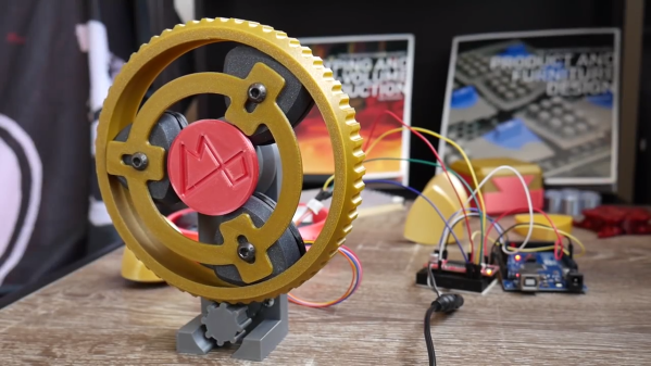
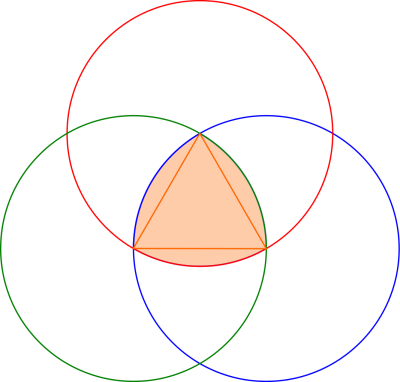
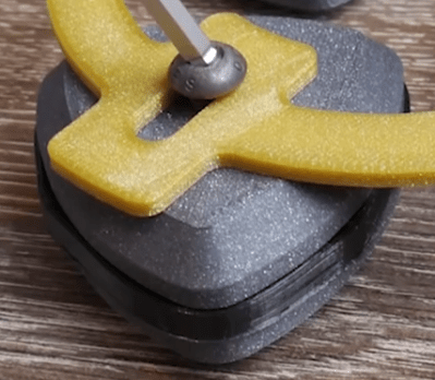
[Angus] finally arrived at a working bearing after a ton of suggestions from the community, and trying a number of attempts until he was able to achieve what he set out to do. The trick was to create a flexible insert (3D printed as well) for the center of the triangle edge, which grips the surfaces the triangle comes into contact with. A frame is also made to hold the bearings in place and allows their centers to move up and down as necessary.

If the thrill seeker within you still isn’t satisfied, maybe you should try the Reuleaux Coaster

Continue reading “The Quest For The Reuleaux Triangle Bearing”