If you’be been hacking and making long enough, you’ve probably run into a situation where you realize that a previous project could be improved with the addition of technology that simply wasn’t available when you built it. Sometimes it means starting over from scratch, but occasionally you luck out and can shoehorn in some new gear without having to go back to the drawing board.
 The two isolated variacs that [nop head] built were already impressive, but with the addition of the ESP8266 he was able to add some very slick additional features which really took them to the next level. He’s done an exceptional job detailing the new modifications, including providing all the source for anyone who might be walking down a similar path.
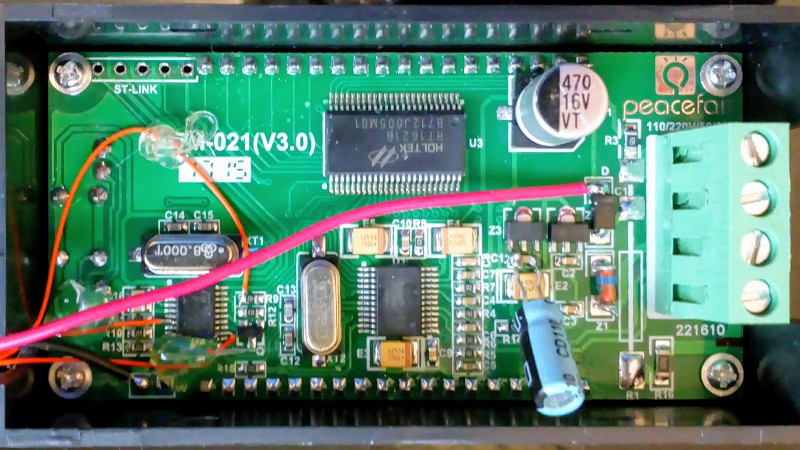
His variacs have digital energy meters right in the front panel which give voltage, amps, and a real-time calculation of watts. After reading an article by [Thomas Scherrer] about sniffing the SPI data out of one of these meters with an Arduino, [nop head] reasoned he could do the same thing with an ESP8266. The advantage being that he could then pull that data out over the network to graph or analyze however he wishes.
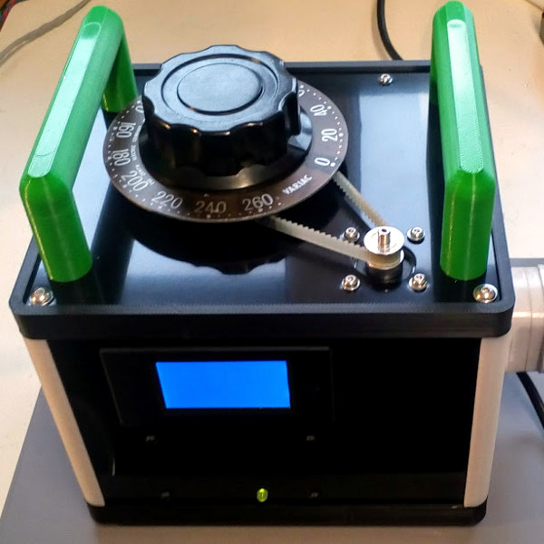
For his older variac, he decided to automate the device by adding a stepper and belt to turn the knob. The stepper is controlled by a Pololu stepper driver, which in turn get’s its marching orders from another ESP8266. He even came up with a simple web interface which allows you to monitor and control the variac from your smart device.
We don’t often see many variacs around these parts, and even fewer attempts at building custom ones. It’s one of those pieces of equipment you either can’t live without, or have never even heard of.


Brilliant, I have a couple of variacs 10 and 15Amps to 270V AC 50Hz,
having a connection to control it with care is great, a link to some HPIB
interface would be of interest bit later of course as my friend up the road
has an EMC lab with all HP gear for high end compliance testing.
Nice one, definitely worth getting into motion control with wifi, so many
commercial and fun opportunities, thanks
instead of HPIB i wonder how hard would be be to use the LXI Standard (ethernet based control of most modern test equipment) over the wifi with the ESP8266
Indeed onebiozz,
Whenever I visit Roman I wonder what sorts of more interesting instrument
and data collection scenarios could be explored and at higher rates too since
HPIB in his setup was last at the then max of 1Mbyte/sec :-(
Eg. All sorts of combinatorial data analytics & intermittent casual tracking.
So in above situation wifi to HPIB would be fine and although HPIB can
be a little tricky with the various protocol interlocks shouldn’t be that
hard to implement on the ESP 32 with perhaps more than one for multiple
channels to assure good data rates with min dropouts.
One of my student projects at Western Australian Institute of Technology
(W.A.I.T) now Curtin University still at Bentley was implementing an
HP1000 to HPIB interface for an architect to run a new type of A0 flat bed
plotter IIRC big enough with minor mods could have done profiling of
polystyrene blocks for the upstairs property developers landscaping.
We did a lower protocol version of HPIB than a commercial card from
USA and still got well paid. I recall my tutor back then was Ian James
circa 1977.
Heck I still a gold plated HP 1000 buss prototyping card not used
and an HP 1000 tape drive !
Come to think of it haven’t been to visit Roman for a while, I got him a
sizable government WAISS grant for an RF anechoic chamber 1999/2000
when I studied some corporate law and lobbying various govt depts.
Hope his NSA coefficient is back where it should be since all sorts of
stuff has been through there (walls fragile) and water damage too…
http://qdl.com.au
Roman graduated a year before I did but, like me has done all sorts
of weird and wonderful projects. Sold him my trusty well used HP 6813A
he upgraded to B version then rented it out – some nutcase put 240V
AC mains into the source analysers output stage – ugh !
I get heaps of stuff from USA via Houston port mostly HP power supplies
many around 1Kw, like the eBay global shipping program too, got a
41Kg HP6269B supply by air to Perth for only AUD $220 – cheap as :-)
https://www.keysight.com/en/pd-1000001534%3Aepsg%3Apro-pn-6269B/dc-power-supply?cc=AU&lc=eng
I have used my DIY 30A variac for years, even recently repackaging it with a power meter that has a serial output recently, it would be quite interesting to give it motor control
Nice one three phase I guess, got a pic ?
I sometimes still come across 1KW 240v 3 phase variacs
and wonder about adding an option switch to allow 3KW
single phase expecting any turns count and brush issues
could be well addressed, heck maybe carefully offsetting
with an NTC thermometer too for start up…
Ugh meant thermister not ‘thermometer’, android auto correct :/
Any chance of a timed edit function (30mins or so) for this site perhaps ?
They help in making a buck-boost adjustable for high powered xenon arc lamps, used to fill in shadows for making Magnum PI episodes. Need a 6v charger for that lil old 60’s Honda mc? Feed your 12 charger 60-70vac, until you can make a charger from a doorbell Xfmr. Yup – I love variacs. Send that and every other new test ckt whatever it wants and will see when implanted into your car or etc without making a supply that will never be used again.
“That means the signals originating from the CPU can go straight into the ESP8266 but the data out from the RN8208G would need attenuating.”
Wrong. See many other posts on this, the 8266 has no problem with 5v logic (not vcc!) What amazes me is people who say this but have never tested it…
in my experience with the 8266 its totally fine with 5V inputs if you put series resistors, without these resistors in my one test i popped my driving microcontroller and damaged an input on the 8266
but i have also seen some people get away without resistors
but needless to say its not good practice to use the ESD clamp diodes as a level shifter as they are not designed for the task and the 8266 does not have a proper 5V tolerant input, working with 5v clamped with the internal diodes for a few hours of testing is one thing, working with 5v for years is a totally different story and with the cost of just 2 resistors its not worth the risk for anything long term
+1
Indeed onebiozz
I’ve seen much of this, also an associate observing a faked differential,
meaning he paired the same ground for carrying other devices is bit
like diff pair from card reader to logger in a vehicle along 5m or so – ugh !
The spec is paramount ahead of what people like to believe and we
shouldn’t assume input won’t latch up too etc. Despite improved fab.
I’ve often seen an emotional desire for simplicity. Resistors of the correct
value are a good start but, can be problematic unless inputs are
proper Schmitt triggers complicated by ground and signal noise
along with flakey code that can be triggered by Vcc out of spec, rare
but has occured, fortunately more unlikely than ever..
Link to my adaptive alternator project in jungles of Malaysia where all
sorts of weirdness happened incl a Gecko wandering over the 300v DC
non 3 phased inverter rails. ie 3 inverters 75 KW not phased as the
local forestry concession operators didn’t want natives using 3 phase
saws for timber – upset others for their 3 phase lathes – ugh…
http://members.iinet.net.au/~erazmus/Power/
I’ve been running both and ESP-11 and ESP-12F for home lighting for nearly a year on 5V straight to VCC. They have not missed a beat. But at the other end of the stick, I’ve has ESP-01 modules that wouldn’t boot if the supply was above 3.580V.
I’ve heard others comment that the ESP-12 will cheerfully run 5V day in day out. so it doesn’t seem too uncommon
I don’t know if it’s due to improved production, or if production yields scale greatly giving vastly mixed quality of chips.
The ESP8266 does not have 5V tolerant inputs. That doesn’t mean if you apply 5V it is guaranteed to fail but it might not work, so shouldn’t be advocated.
It is the same with all electronics. If you run components within their ratings they are guaranteed to work. If you run outside the ratings they are not guaranteed to not work, it is undefined. Semiconductors vary widely from batch to batch. The manufacturers reject the chips outside their ratings but many will exceed them greatly and only a few just be borderline passes.
You might get lucky in a one off build but it if you want to ensure a design works every time for everybody then you need to observe the ratings.
+10 nophead
Seen this many times during my many personal
visits to Sham Shui Poh in Kowloon, not that there
is a sham of any sort ;-)
But, since tuesday markets have streets hawkers
selling tubes/reels of electronic components and
adjacent to a man poking his pet cobra then you
can guess all sorts of oddities just to sell product
with no care or responsibility other than the
casual way they exploit “planned” obsolescence…
Now I’m dealing with odd ball electric field effects
in pre-thunder clap situations where an EMP tuned
equiv length from MOV leads has issues – geesh !
Thank the stars for great instruments and good
support across time-zones – phew :-)
There has been work done on this before, and expressiff even said so ie
“Espressif CEO Mr Teo Swee Ann commented that “i can reply officially here: it is 5V tolerant at the IO. while the supply voltage is at 3.3V.””
See https://www.ba0sh1.com/blog/2016/08/03/is-esp8266-io-really-5v-tolerant/ for a good write up.
I’ve now been running 8266s connected to 5v devices, that have been running continuously for 2 years. No problems.
So I wish all these people saying it can’t be done would actually try to do it. 5v on VCC might depend on the batch, BUT 5V for the digital IO is FINE.
All this talk about 5V tolerant.
Hello?
Most of these things are clones of clones sourced from Alibaba, and you’re going to trust the original specs?
It depends. For some microcontrollers the inputs are well specified for clamping currents. The manufacturer even states how much such a current influences the performance of the neighboring pins (logic threshold and ADC). Other mfgs or µC series explicitly forbid any DC current through the diodes.
No snarky comments about how IoT is out of control and somebody is gonna hack this variac into a botnet?
Just yours so far…
B^)
Meant in the article, I guess I’m used to Benchoff complaining.
I don’t use my Variac much, but it is worth its weight in gold when I need it.
This is a neat mod indeed!
I grabbed one which was being chucked at work.
I don’t know what I’m going to use it for yet.
So it is sitting waiting to be enegised.
Ideas most welcome.
I quite fancy adding a stepper to it. Just, well, because.
LoL, we had a variac upstairs at Pretron Electronics in 1985,
our apprentice electrician Barry wired the cleaners common
power point they use to vacuum the floor as its on the end
of our bench (office ones on telex & PC’s no touch). Since
we had to stay back that day for major rewiring and the
cleaner came through around 6pm – we were ready and
pretended to ignore her after a low key wave…
So she plugged her vacuum in and proceeded to swipe
then Barry gradually powered the motor down with
perplexed reactions from her (can’t recall her name) then
Barry wound it up high a few times as if revving a car,
then back down again and repeat about 3 times. I recall
Barry wound it down to a stop part way through then fast
back up and I burst when she jumped !
As much as we tried we couldn’t contain ourselves and had
to own up, she went red & was pretty angry for a while, rest
of the week was a bit awkward.
Got her a bottle of Shiraz end of week with a single carnation
:sigh:
“Got her a bottle of Shiraz end of week with a single carnation”
Well played. sir!
Thanks,
I must concede I was main driving force, Barry was stunned his
boss would even think of such a thing especially as I seemed
to him at first as so staid and conservative being 20yrs older.
Now that I’m trialing a few of my own high mineral supplements
I fear my earliest youth habits returning with a vengeance in the
oddest yet most entertaining ways for more fun, eeks stay away ;-)
https://www.google.com/url?sa=i&source=images&cd=&cad=rja&uact=8&ved=2ahUKEwiN7t3dhIjbAhVl54MKHXD6CmEQjRx6BAgBEAU&url=https%3A%2F%2Fme.me%2Fi%2Fstay-thirsty-my-friend-memes-com-10272299&psig=AOvVaw1UX13TgsF1bGKTSTEpjBk8&ust=1526484686527285
LoL :-)
Site resolves to this unless my google pattern very different, food for me mates, tah
https://me.me/t/friends
Hey I got a google whack ie only one in all of google if I believe it !
https://www.google.com/search?q=%22bottle+of+Shiraz+end+of+week+with+a+single+carnation%22&ie=utf-8&oe=utf-8&client=firefox-b
“What tangled webs we weave when we set out to deceive for alas it is ourselves in all we perceive”
Give it a few mins ;-)
“An article” might just have been https://hackaday.com/2016/07/11/put-a-reverse-engineered-power-meter-in-your-toolkit/.
I just stumbled across these pages last week looking for an DC-DC efficiency meter (which I did not find), and one of those meters is on its way for my variac, which has not been motorised yet (but the thought crossed my mind). Good stuff!
+1 None, nice one
Didnt know about this project. Have been collecting more
background last few days as prep for a report – looking good,
going to be a busy w/end, thanks
I dunno, I don’t have a problem turning the knob on mine. Mine even has a dial on it to give you a rough idea of what the output is set to. For me turning the knob is much easier than having to screw telling a computer to do it via a web interface.
Ah well some do know ;-)
For what it’s worth I suggest look beyond the surface and see
this as a tool as part of a larger potential such as a component
towards automated testing, spec verification, education, the
handicapped, feedback logging, other etc
Eg. I’ve seen lots of people do what at first appears to be one-offs
like this which at first glance seem to offer only appearing as
onerous then discover extensions. I now recall an HPIB to
serial converter so going from a PC as instrument controller
to devices like this in an ATE environment most helpful.
The fact there is now proven means to control power
remotely and at comparatively low expense and methods
easy to implement offers a few interesting commercial
opportunities especially less obstacles to overcome :-)
Cheers
When it powers up the motor is not energised, so I can turn the knob and use the dial as normal. However the mains voltage in my house varies continuously, so without the computer control it is very hard to get make accurate assessments of line regulation of power supplies, which is what i actually use it for.
Use a true-Sine inverter & DC power source…
Indeed, I recommend the HP6813B which I expect
is now superseded – go for a UPS DC linked 5KW
equivalent then can run your big screen TV and
fridge next to the lab with all the logging instruments
still running on auto when you need a rest, should
also be able to run the massage/nap recliner ;-)
But do not use the cheap one, I have. If you want to start a 400W universal motor on the supposedly 600W/1200W_peak unit, the voltage drops down to something like 100V (instead of 230V) and the current was 0,3A. The motor turning really slowly. I had expected it to limit the current to it’s nominal 2,8A and pushing whatever voltage occurs – no! Another power tool with about 400W takes about 30s to come to speed, but then you can use it.
+2 good stuff nophead,
Does the motor energising go through some CPU
& s/w fail safe scenario ?
ie. Circa 1985 I hired an Engineer Vince Lipton
to move the co forward under our tech director Eric
to design an uprated IR guarding system for
press brakes and metal guillotines OHS issues,
so machinery wouldnt cut off body parts etc…
Vince employed a tight PFM driver for the enable
relay(s) so if a design numb nut had a s/w glitch causing
any sort of oddity it would de-energise any power drivers
to the equipment’s hydraulics automatically within mS.
My part mostly supervising Z80 then to NSC800 on
aspects of RTC operation as in No ie Definitely NOT
have any interrupt driven pulsing of any kind – all power
drivers timed in back-ground with preloaded stack return
addresses in event of power glitch stack failures and a
few other niceties making it as bullet proof as possible
with of course some back up hardwired logic. Lots of
noise screening, hidden micro-switches etc.
Suffice to say all power driver BJT’s also had sense
logic interlocks and 10+ times over-rated. In my role
at Pretron Electronics sold heaps for their Nova Machinery
division of metal forming/cutting equipment…
19 King Edward Rd, Osborne Park, Western Australia
Then some bean counter sold the cash cow o/seas
and the co collapsed 1988 ie.The short term gain far
below any sort of strategic value over even 2 yrs ROI
with nil consideration of tactics accomodating 1987 ‘crash’…
But anyway, yeah keeping things well within spec
is an ideal and anything less is incompetent in any
sort of production environment. For health and
safety one must go that bit extra ++ and even then
prudent to have interlocks + multiple fail-safes :-)
Cheers
“I dunno, I don’t have a problem turning the knob on mine.”
Sometimes, one does not want to be in the same room when powering up an unknown factor via Variac!
B^)
+1
Ah is this the rising AC volt thermal soak test on a solid tantalum
capacitor jammed in a used white board marker ;-)
I would not like to do experiments in my apartment where I have to fear to be in the same room. And if I power something unknown up with the variac I probably want to monitor current and voltage closely anyway.
But of course the remote control/automated control option is a nice feature.
This is really true. A meter would be nice, but remote control is quite unnecessary for my applications. I only should finally fit the inrush current limiter. I do not use the variac often because it trips the breaker with 50% chance.
But its really nice to test repaired switch mode supplies to avoid “back to square one” if you forgot something.
On an only semi-related note, does anyone know of any guidelines for deciding the capacity of a variac that came to me missing it’s enclosure?
I saved it from a scrap heap, but the shell had been shattered, other than a few remnants of what appears to be Bakelite.
I haven’t used it yet, but was thinking to evaluate it based on the copper wire gauge, and maybe de-rate it a bit below current wire gauge standard ampacity.
Ah an interesting problem there Josh,
First check no wire damage especially
if brush fragments shorting coils…
You can be pretty sure it’s 110v or 220/240v
depending on where you are and might just
handle with 50 and 60Hz too if a higher specd
lab unit not the type used in schools.
If u in US most likely 60Hz so start on that posit.
Hey it might even be a dual brush type for the
centre tapped setup then it’s a
All you need to do is feed it with another known
Variac and measure the current your unit draws
as you gradually set the known unit up from 0v
to say the normal 110-115. Ie current meter on input
of unknown unit.
At first no load on yours and start on yours
at the 0v setting also. The above gives you
a starting point re magnetising current.
Wind it up to the normal US range and record etc.
The rest are just fairly obvious permutations when u
start adding linear loads, high W light incandescents
or bar heaters etc. Of course observe/test wire temp
with an ir non contact temp meter, though you can find
the inflection from Delta input current which, if
properly designed and no hidden damage will occur
well before Delta wire temps max rise rate…
ie. Watch for highest current rates of change up then
you have established various upper bound conjunction
of volts and current. Eg graphing it too for reference,
takes about 15mins all up. This method is rather good as
in definitive or take a simpler route based on fixed loads
in conjunction with wire size as you mention.
Good thing with the longer method is you get a set of
curves which are ideal in a lab environment :-)
We used to do something similar with various electric
motors feeding variable hydraulic loads at Nova
Machinery circa 1984 to 1987 part of the press brake
manufacturer Westralian Equipment Group.
Good luck & come back soon yah hear :D
Rest of first main para, dropped off switching
between voice and touch pad input few times,
Lenovo with Android eek…
Hey it might even be a dual brush type for the
centre tapped setup then it’s a specialised
unit suitable for compliance testing. Despite
common use of centre Tapping 220 to 110
in two strings. I expect not that common.
Thanks for the tips and guide for evaluation and testing this variac.
Now I’ll have to see if I can find another to test mine with.
Np, on reflection you don’t have to go as far as I
do, I’m just used to lab procedures and reliability
of outcome as my neck can be on the line angry
I wont make profit that month ;-)
As yours is mostly a casual test, then first put the ohm
meter on the input winding with the output open circuit
and go through range bottom to top, this should show
up any wiring breaks and give you a starting point,
Also do ohms test on any case, knob etc to any of
the AC wires for basic safety test,
Then power by mains AC through a high watts lamp in series
with input, cycle it up and down whilst measuring current.
and measure open circuit output volts. Make
If above passes than take out the lamp make sure a suitable
sized fuse in place and repeat cycling then take it from there.
If it doesnt pass then maybe a diff frequency or the core
damaged in some way so the magnetising current excessive.
Either way with above don’t need another variac :-)
Cheers
I just received a PZEM-021(V5.0) and it is based on a Vango
Technologies V9821S “Low-power Multifunctional Energy Metering SoC” with
“enhanced 8052 MCU core”, so no STM32 and no sniffing SPI.
Damn! I have second one that I actually ordered before the one I used but it took too long to arrive from China so I bought the one I used locally. I just opened the slow to arrive one and I is a V5 with the new chip.
It does have a serial link to the display controller that could be sniffed but it isn’t SPI, it has separate read and write clocks. Possibly they could be ANDed together to read it with SPI. But the data would be pixels so a bit of a job to turn it back to digits.