Transmission lines can seem like magic. When you make use of them it seems strange that a piece of wire can block or pass certain frequencies. It is less common to use transmission lines with pulses and typically your circuit’s transmission line behavior isn’t all that significant. That is, until you have to move a signal a relatively long distance. [Robert Baruch] has been using a long PCB to test pulse behavior on a bus he’s working on. He actually has a few videos in this series that are worth watching.
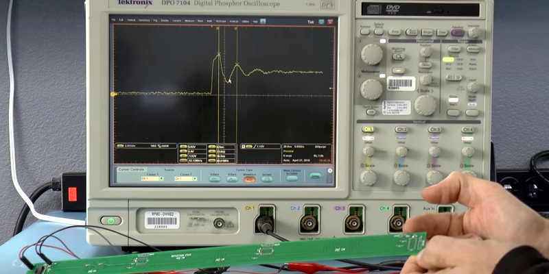
What makes it interesting is that [Robert] has enough distance on the board to where light-speed effects show up. By using a very nice DPO7104 oscilloscope and a signal generator, he shows how the signal reflects on the line at various points, adding and subtracting from it. The measurements matched theory fairly closely. You shouldn’t expect them to match exactly because of small effects that occur randomly throughout the system.
Before you decide you want to run out and buy the same oscilloscope, you better check your bank account. The cheapest used one we could find was about $5,100 and most were double that (possibly due to installed options; we lost interest in looking). A new one is quite a bit more.
It would be really interesting to build a board like this for showing how a half wave or quarter wave stub shorted at one end can act like a filter. In fact, it isn’t so magic if you think about how currents flow in an antenna. Transmission lines can be on a PCB like [Robert’s] but you can also make antennas out of PCB traces.


A schematic would have been nice. I stuck with it until about half way then he seemed to be saying he is driving the chip output into a direct short through some PCB tracks and still getting voltage without smoke so clearly a chip and PCB that can handle infinite current without blowing up.
An infinite current would happen only if the voltage source (the generator) is ideal, AND the generator have zero output impedance AND the generator is generating DC instead of a square wave AND the time is also infinite. In a transmission line, or any other AC circuit, things are very different from a DC circuit, especially for fast transient signals and/or transmission lines.
In reality, the pulse generator has an output impedance, so if you short-circuit the output of the generator, the maximum possible current will be limited by the output impedance of the generator (which is usually 50 ohms for standard signal generators).
The equivalent circuit for the signal generator is an ideal source (0 ohms) of pulsed voltage, in series with a 50 ohms resistor. The rest of the circuit is made just of two parallel PCB traces with a resistor (or a short circuit) at the other end of the PCB traces.
It may be a short *at DC*, and you may think that’s a bad thing, but remember – wires aren’t what you think wires are.
It’s a transmission line with one end terminated with a short. (The effect is almost identical if an open circuit is used, but the phase of the reflected signal is flipped around. (The imaginary component of the S11 scattering parameter would change sign, in theory, if you had the cable plugged into a VNA port.)
In the meantime I’ve watched the video, and there are a few misconceptions there, like the reflected edge would _increase_ the voltage (it can also decrease the voltage, increase or decrease depends only of the ratio between the impedance of the transmission line and the impedance of the terminator – if the terminator’s impedance is lower than the impedance of the transmission line, than you will see a decreasing voltage step instead of an increasing one), also, the lenght/time of ringing is not dictated by the lenght of the transmission line, and so on.
The video is not exactly wrong, because in the very particular case of a low impedance source, a higher impedance transmission line and an even higher impedance terminator, the affirmations in the video stand true. Yet, these are only particular cases, so I think the video might confusing. A better grasp of the transmission line is necessary in order to properly explain what is seen on the oscilloscope.
w2aew have a few great and concise videos about transmission lines, highly recommend. In this one, at minute 09:17 it can be seen how the reflected voltage might add or substract, according to the ratio of Zline/Zterminator:
https://www.youtube.com/watch?v=Il_eju4D_TM
For a complete understanding of the time domain in transmission lines, these classes are very good:
https://www.youtube.com/watch?v=7Oz1sazpekM&list=PLULkq8AIoZ7zDTvbaWW9RvXR8Ngnpe0s8
I agree that it’s not entirely clear what he’s doing all the time.
But I think you have misunderstood what he’s doing: I think he’s experimenting with source termination, which means a resistor between the driver and the PCB track. In other videos he’s experimenting with load (or end) termination.
So basically if he has a short in the source, then the impedance of the driver determines how hard you’re driving the PCB track, but certainly not with infinite current.
Frequency is a huge factor. I’ve used a number of excellent transmitting antennas over the years that were shorted at DC but a good match at 146 MHz (or whatever other amateur radio band I was transmitting on at the time). I’m sure there are other factors involved, but I’m just not smart enough to get into the science of antennas and feedlines.
A humble oscilloscope like Rigol DS1054Z (~$400 new, has 1GSa/s, so 1ns time resolution), a few meters of coaxial cable and a couple of resistors is enough to experiment with transmission lines and TDR (Time Domain Reflectometry).
In theory it should have a resolution of about 30 cm of light path (12inch), in practice, it was very easy to distinguish the 1…1.5 meters BNC cables between the standard 50 ohms coax cables and the 75 ohms coax cables used in audio/video by simply terminating the cable with a 100 ohm potentiometer, then adjusting R until the stair step disappear.
We bought one of these 7104 DPOs about a decade ago (1GHz – 4 Channels), it was around 25k$ if i remember correctly. One 1GHz active probe alone sets you back a few 1000$…
I must admit tho, a lot of termination problems are very hard to measure in circuit. We had some issues with a DDR-RAM interface, and the easyest way to see the effect was in the anechoic shielded chamber by performing radiated emission mesurements.