
One of the great joys of Hackaday are the truly oddball requests that we sometimes get over the tip line. Case in point: [DC Darsen] wrote in with a busted 1970s organ in need of a new top-octave generator, and wondered if we could help. He had found a complicated but promising circuit online, and was wondering if there was anything simpler. I replied “I should be able to get that done with a single Arduino” and proceeded to prove myself entirely wrong in short order.
So we’re passing the buck on to you, dear Hackaday reader. Can you help [DC Darsen] repair his organ with a minimum amount of expenditure and hassle? All we need to do is produce twelve, or maybe thirteen, differently pitched square waves simultaneously.
Top-Octave What?
Pipe organs make sound by vibrating air in tremendously large tubes, one per pitch. Then along came the Hammond organ, which from 1935 to the mid 1970s made sound by spinning metal disks with periodic cutouts in the presence of an electronic pickup. A Hammond is still not a small machine, but it was positively compact compared to the pipe organ. By the 1980s, all of this sound generation could be contained in a dedicated IC, ending the era of the giants. (At least for mass-market instruments: a real pipe organ in a big space is still a delight to hear in person.)
But for a brief period of time between the tonewheel and the VLSI eras, there was a decade of home organs that were designed with the readily available wonder technology of that era, discrete logic ICs. In particular, these designs leverage the ability of a flip-flop to take an input frequency and divide it by two easily and cheaply. Dividing a frequency by two lowers its perceived pitch by an octave which meant that, if you could accurately generate one pitch for each of the twelve tones in the scale, you could use flip-flops and divide down to cover the entire keyboard.
Reference Pitch Chip
 Providing an accurate set of twelve reference pitches is the job of the top-octave generator (TOG) chip, a part which isn’t made anymore. But what if you want to repair a 1970s organ that used them? You might be able to order expensive old-stock spares, but where’s the fun in that?
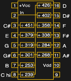
Almost all of the TOGs took an input frequency derived from a 2 MHz crystal oscillator circuit and provided twelve or thirteen square waves of the right pitches by dividing this input frequency by factors from 239 to 478. If we had to implement this in silicon, we’d build up twelve 9-bit counters, all driven by the same 2 MHz master clock, and cause them to reset when the right counts were reached. This should be easy to replicate in firmware on an Arduino, right?
Microcontroller Non-Solutions
The highest “C” on a piano clocks in at 4,186.01 Hz, meaning that we’d have to toggle a pin approximately every 1,911 cycles for an AVR ATmega Arduino clocked at 16 MHz. One pitch would be easy. This might suggest that you could implement this naively in software, keeping track of twelve counter variables and testing in a loop if each should be reset.
while (1) {
    C7_TOGGLE;
        for (volatile uint8_t i=0; i<12; i++){
        if (counts[i] > tops[i]){
            counts[i]=0;
        }
        ++counts[i];
    }
}
But it doesn’t scale. If you implement it this way, the time between counts is simply too long, and you’re unable to define any of the pitches accurately enough that it’s musically useful. The loop above runs around 20 kHz, which is nowhere near fast enough, and all the pitches are out of tune.
An alternative approach would be to let a hardware timer run free, set up a timer variable for each oscillator, and toggle each oscillator when its individual time is reached and then update the GPIO pins.
But because the divided-down oscillators are running at different frequencies, even with only two such oscillators, they will phase in and out. Eventually two transitions will come so close to overlapping that going through the loop takes too much time to service them both, and one will reset late. With twelve oscillators running, the resulting jitter is audible, and it sounds horrible.
These concerns, and a desire to do away with the flip-flop dividers, is what lead Tom [Electric Druid] Wiltshire to build his TOG with twelve PICs, one for each note of the scale. To run in tune together, though, they need to run on the same master clock, and Tom reports problems with the PLL he was using as a master clock. I have aesthetic concerns with using twelve PICs, though I suppose it’s not worse than using twelve synchronous counter ICs for the octave divisions.
Most microcontrollers have onboard hardware timer circuitry that can do exactly what we need, but twelve independent timers is pushing it. An ATmega-powered Arduino has three hardware timers, and one is tied up by the Arduino firmware. If you’re willing to ditch millis(), you could implement three of these oscillators in hardware and probably run a fourth on the CPU. You’d only require three Arduinos for a full octave. We might be getting somewhere.
Overkill, But Plausible
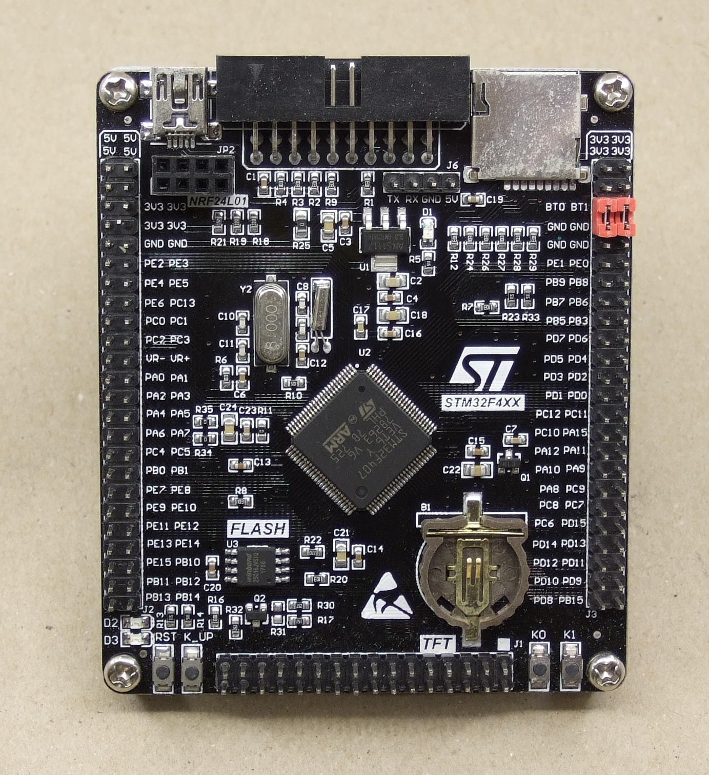 Some fancier microcontrollers have twelve or more hardware timers. I looked around and found that the high-density STM32F407 boards, which are available for not too much from the usual sources, have twelve 16-bit timers. I’m not sure if all of them are available, or operable at once. Still, the all-hardware approach has the advantage of rock-solid timing, and 16-bit resolution on the pitches is an improvement over the old-school TOGs. But throwing a higher-end microcontroller at the job just to leave the 168 MHz CPU completely idle seems somehow wasteful.
A TOG is actually a perfect application for an FPGA. You could implement the divide-down-by-counter design of the original ICs fairly faithfully, and each of the sub-circuits in and FPGA run independently and truly in parallel. Implementing the flip-flops for division would be easy enough as well, and as long as the FPGA has 88 free output pins you could generate all desired pitches in one piece of silicon. That would be pretty sweet.
Your Turn
My gut feeling is that the FPGA solution is the best, although it won’t be DIY-friendly for the majority of organ-repair hobbyists. Everyone knows Arduino, but syncing up three or four of them sounds like trouble. The high-end microcontroller solution should work, but feels wasteful.
What are we missing? Where is the clever hack that will allow twelve independent timers to run in software on a single AVR Arduino? Just for the mental exercise we’re really interested in hearing a working microcontroller solutions. But maybe you have some secret trick to keep a dozen 555 timers in tune? (We’ll believe it when we hear it!) Anyone want to show us how easy the FPGA solution could be? How would you implement a TOG?


I would have thought that something like this would do the trick https://www.idt.com/products/clocks-timing/jitter-attenuators-frequency-translation/8t49n1012-femtoclock-ng-12-output-frequency-synthesizer
You may need a further clock divider to get down to the frequencies you want (8kHz seems to be the minimum for this part), or there may be a similar part that goes to lower frequencies, but generating clocks ought to be a more-or-less solved problem by now…
FWIW, I also think that the FPGA route might be the simplest. Failing that, it may even fit in a CPLD, making it cheaper and easier for the hobbyist. There are a bunch of cheap and cheerful boards around that could do this sort of thing. https://www.digikey.com/catalog/en/partgroup/xc9572xl-cpld-development-board/58754?utm_adgroup=Programmers%20Dev&slid=&gclid=EAIaIQobChMIrKLuxMOe2wIVCR6GCh1FLgTFEAAYASAAEgIRQ_D_BwE
You can get these for $4, “XILINX CoolRunner-II FPGA CPLD XC2C64A Core Module Mini” on ebay, but is 64 macro cells and 1500 gates enough?
You would need 106 registers/macros just for the counters
Use some of them boards the xbox modchip people use. Else get on the phone to Sam Zelloof (Homebrew IC guy)
Yeah, this sounds like a very good application for a small FPGA (maybe even just a CPLD). Would probably make a reasonable first FPGA project too; it’s relatively simple but still makes good use of their capabilities.
That was my thought too, although I’ve never done a GAL, PAL, FPGA etc…
All those gates inside one could be built in counters, right?
But, I wonder if it could be multi-voice, i.e. able to generate chords when multiple keys are pressed.
It doesn’t need to. All it does is takes one 2mhz input, outputs 12 reference frequencies as divisions of the 2mhz tone, then each of those goes to flip-flop 2:1 frequency dividers in a long chain to reach the bottom octaves.
Keys simply connect a tap somewhere along that line to the mixer/speaker.
Further dividing down 2 Millihertz will give you “geologic” frequencies :-)
What’s wrong with just implementing it in discrete logic ICs? Yeah, you’d have to lay out a PCB, but 2 MHz clock is slow enough not to be too much trouble.
Nothing’s wrong with it, if you’ve only got to do it once. :)
Twelve counters, and however-many ANDs per channel should do it. You’re looking at a board with 40+ ICs on it, before the octave dividers. It’ll be impressive!
Elliot,
I do like this type of article, “Ask Hackaday Readers” not confined to Fail of the Week.
I hope we see more.
+1
You can avoid the AND gates by using presettable counters, and just using the high-order bit as the output. This will be asymmetric, but that’s easily cleaned up with a flip-flop.
The problem with doing this with MSI counter chips at all, is that the divider ratios needed require a 9-bit counter. That’s what makes FPGAs and CPLDs the better choice.
Yes, overall they seem the better choice here. The big advantage of the MSI solution is, that you do not need to program them. I had an FPGA in my diploma thesis project. Fortunately it was possible to do the design on a schematic base with counters and flip-flops in the same program (viewdraw) that I used for the PCB schematic and I did not have to translate circuits into a programming language.
I think it was Bob Pease:”My programming language is solder.” :-) I completely agree.
Most HDL IDE’s support schematic entry now. Though that’s only useful for smaller projects like this.
It words. Here is the math: https://en.wikipedia.org/wiki/Equal_temperament You can even explore the rabbit hole of alternative tunings.
TMS3617 top octave generator chips are available on Ebay. Why reinvent the wheel?
Ergo
https://www.ebay.com/itm/TMS3617-Top-Octave-and-Keyer-IC-Chip-TMS3617NS-Tone-Generator-Genuine-US-Seller/222915205798?hash=item33e6c81aa6:g:3cUAAOSw3MpayYXr
But the Aliexpress link in the article to the STM…….7 is half the price of the TMS3617.
Using assembler, it should be easy enough to do on Arduino. Instead of trying to count in software, just put a hardcoded delay between the toggles.
Something like
nop
… ; N clock cycles
nop
toggle pin 1
nop
… ; M clock cycles
nop
toggle pin 2
nop
…
goto start
Figuring out how many nops to put between each toggle shouldn’t be too difficult even with just a pen and paper. And it is certainly a fun introduction to assembler coding, because it doesn’t need anything too complex.
(Note: this assumes that the lowest common multiple of the individual periods will fit in the flash of the device.. shouldn’t be a problem I think, and if it doesn’t one could use a delay subroutine instead of bunch of nops.)
I just typed those numbers into an LCM calculator and the result I got was… 8340422077028761600.
That is one big-ass state machine. I don’t think this is the way to do it.
I don’t think lots of nips is the answer, but I’d be surprised if an assembly-based version of Elliot’s original attempt didn’t work.
It seems counter-intuitive that a (relatively) extremely fast IC can’t manage 12 simultaneous tones, so I wonder if the compiler is making a mess of it, or if unfolding the for loop and array would help?
Also there may be interupts running (like millis()) which could be turned off.
Also worth considering the tuning scale – if the organ were tuned to a key, rather than a generic tuning, it might significantly simplify the ratios between notes.
It is indeed counter-intuitive.
Unrolling the loop, eliminating indexing (just use 12 separate variables), and making sure interrupts are off would all help, but they aren’t enough.
Sooner or later two or more pins will need to toggle closer together in time than the time it takes to determine which pins to toggle. I’m pretty sure a 16 MHz AVR programmed in assembly could do 2 tones decently, but not 12.
Using some form of just intonation (simple ratios between notes) rather than equal temperament might help, but it will also make the organist unhappy. It’s pretty much required to have the 2 ** (n / 12) ratio between notes that are n semitones apart.
In the end this is a job for hardware, which is probably why chips with lots of on-board timers have been around since at least 1989 (MC68332).
The solution is simply running the loop slow enough that you can calculate the appropriate bits and overlaps.
But how then do you generate the high frequencies?
Simple: you push the notes through a low-pass filter which effectively turns a square wave into a triangle wave, then rectify the wave with diodes, which doubles the frequency. Then square it up again with a schmitt-trigger buffer.
You can keep re-doubling the frequency as long as there’s enough voltage overhead or buffer amps.
Using a top-octave generator that uses separate divisions from a 2 MHz clock is already not equal temperament. As I’ve already said somewhere in here, the ratios between frequencies in the scale in equal temperament are all non-rational, so it’s impossible to do better than an approximation when using division (or using any phase accumulation algorithm, which is effectively just division using a bigger denominator). The use of division of a 2 MHz clock is already a simplification; it was the value that at least one designer found to be close enough to play in most keys without unpleasant effects.
Not that this is a bad idea – I had a Casio keyboard from around 1980 that appeared to use just intonation, which sounded just fine in the keys of C, G, and a couple others, but got downright ugly in others. If you have a number of different tunings (up to 12), you can definitely get better results out of a lower clock frequency, although that may not necessarily be something convenient like 2.000 MHz. You could certainly synthesize a clock that would be best for any given key, and this would then simplify the tone generator since it would be using the same divisors in all keys. But that wouldn’t be very convenient because it would make it a transposing instrument – they physical keys would be different notes in every musical key. Some might see this as an advantage, though, so it’s something to think about.
I tried working this out mathematically, but that way lies madness – probably the best way to do this would be to do what the guys a Casio did: pick a clock frequency (hopefully something well below 2 MHz) and just find the best set of divider ratios for each key.
Glad someone mentioned temperament. It might only upset organists. Instruments once were, and many still are, tuned to play in a specific key, where all the main notes are spaced at nice integer ratios. If you were willing to take that approach, the maths is easy. You just have to choose a key/scale to play in, and preferably means of selecting a different one. It’ll upset the organists, sure, but talk to a brass or reed player for contrasting opinion. (My son plays trumpet and will use different fingerings for certain notes depending what key the piece is).
A CPLD definitely sounds like the way to go, and keep the scope to just replicating the TOG. Might be able to pull this off with a coolrunner, which would be pretty similar in cost and size to an Arduino.
Why is [Sir] Elton John dressed like Donald Duck?
If you can remember the 70’s, you weren’t really “there”.
http://ultimateclassicrock.com/elton-john-central-park/
What I can’t figure out is why, when I look at the illustration, I hear him singing “Saturday Night’s Alright For Fighting”.
Thanks for the link, I’d never heard/seen the concert. (Not surprising, I’d lost all interest in EJ by that time)
You could unwind the for loop to avoid the incrementing and comparing.
You could also write the code in such a way that it will not take paths of different lengths depending on whether it’s time to reset a counter or not.
You could even compute the value to poke in the GPIO register before and then set multiple pins at once but your biggest problem would be the fact that at some point you’ll have to toggle two pins that use two different registers.
It would be easier to count your cycles in ASM and insert NOPs to make sure your loop time is precise.
https://www.youtube.com/watch?v=MdIfUeldIxg
Use one counter, precompute the bit flips and delay table as needed, have a timer with a compare interrupt that immediately flips the outputs then reloads the counter. Might have to put in some special logic for close-spacing of flips to either coalesce toggles or do fast re-triggering but it should work just fine. Otherwise an ice40 or GreenPAK chip would be perfect if you want to go the programmable logic route.
That’s a perfect job for 12 NE555s!
Would someone please think of the temperature-dependant frequency drift?
Nothing a huge aluminum plate heat sink bonded to all the chips couldn’t handle.
B^)
Or use point-to-point wiring and bond them around and along an aluminum/copper rod; three rings of four, or four rings of three, depending on rod diameter.
Temperature controlled oven?
Use a microcontroller to measure the frequencies and adjust with digital potentiometers?
A set of 12 555s (or 6 556s) would be an improvement over the original. The ratios of frequencies in the notes of the 12-note scale are irrational, and therefore cannot be accurately generated by division. The best you can hope for is an approximation, and dividing down from 2 MHz back in the day was a compromise between accuracy and cost. To generate A-3520 (three octaves above 440), you need a divisor of 568.1818…, and the closest you can get with an integer is 568, producing a note at 3521.1 Hz. If you played that against other well-tuned instruments, you’d get a 1.1 Hz beat note, which is something that doesn’t take a well-trained ear to detect. The errors get smaller as you divide this down for lower octaves, but they’re still there, and in those higher octaves, chords have the wrong internal beat notes, making the instrument out of tune with itself.
This is my one criticism of the Hammond B3, which is otherwise a superb instrument. But those tone wheels are locked together, effectively generating specific harmonics of the motor’s rotational frequency, so the intervals are always too perfect, or just not right. Again, they’re just an approximation, because the notes of a chromatic scale are irrational.
Furthermore, the pitch ratios are always EXACTLY the same, which is not a good emulation of analog oscillators, i.e., the organ pipes being replaced. Two notes played together will always produce the exact same beat note, which is unnatural.
With analog oscillators you can tweak to your heart’s content, and you have the bonus feature of being able to do differently-tempered scales. Using 20-turn trimpots, you can easily tune these oscillators to well under 1 Hz. Or even, as JDX suggests, use a microcontroller and digital pots to measure and adjust the frequencies.
Comparing beat frequencies is useless. Real-world instruments are never perfectly in tune. Pianos even intentionally detune the multiple strings struck by any hammer in order to intentionally create a beat.
Talking about JNDs, on the other hand… That high C divider of 239 is precise to within 1/(239×2)=2092ppm ; a JND of 6 cents is 2^(6/1200)-1 = 3472ppm. The results of the top-octave-generator are going to be as good as any other equal-tempered instrument.
Analog oscillators can be stable enough, but if the lower octaves are just going to be generated digitally anyway, it’s not clear there’s an advantage in starting analog.
rnjacobs:
“Comparing beat frequencies is useless. Real-world instruments are never perfectly in tune. Pianos even intentionally detune the multiple strings struck by any hammer in order to intentionally create a beat.”
Not true. Human ears can HEAR beat notes. Pianos, being string instruments excited by percussion, can support multiple modes of oscillation simultaneously, which is why the overtones of any string are not perfect harmonics. For piano strings or any other resonator excited by an impulse, their overtones are out of tune with their own fundamentals, even for single strings. I used to tune pianos, and know how this works. This contributes to the richness of a piano’s timbre, and also covers a host of imperfections, because there are beat notes beating against other beat notes. A big factor in the art of tuning pianos is avoiding unpleasant beats. But for instruments that use air columns as resonators for fluidic oscillators, such as organs, these only support generation of perfect harmonics, so the beat notes between different organ pipes are easily heard. In real pipe organs, this is mitigated by using multiple ranks of pipes that are not perfectly tuned. This is not the case for top-octave-driven electronic organs.
“Talking about JNDs, on the other hand… That high C divider of 239 is precise to within 1/(239×2)=2092ppm ; a JND of 6 cents is 2^(6/1200)-1 = 3472ppm.”
You miss the point again. Absolute errors, measured in percent or ppm or whatever method that indicates a ratio between frequencies, may sound incredibly close, but miss the beat note problem. If you have two oscillators, one running at 10,000 Hz and another at 10,001 Hz, these only differ by .01%, or 100 ppm. Which sounds pretty damn close. But if you play both of these through speakers, you will hear a very pronounced 1 Hz artifact as the two go from being in phase to out of phase, and back. I agree that this seldom comes up in acoustically-generated music, because there are other factors like vibrato and tremolo that make these much more complex. But for electronic music this can be a big problem.
“The results of the top-octave-generator are going to be as good as any other equal-tempered instrument.”
This would be true, if a top-octave generator WAS an equal tempered instrument. But it is not, and cannot possibly be, because the frequency ratio of any interval in equal temperament is a power of the twelfth root of 2, which is an irrational number. Which by the definition of rational means that you can’t derive most intervals using division. The only exceptions are the unison interval, which is the 0th power of the 12th root of 2, or 1, and the octave interval, which is the 12th power of the 12th root of 2, or 2.
“Analog oscillators can be stable enough, but if the lower octaves are just going to be generated digitally anyway, it’s not clear there’s an advantage in starting analog.”
Because it’s the pitch we’re talking about, and it takes a clock frequency quite a bit higher than 2 MHz (or very small phase increments in the case of a phase accumulation synthesizer) to NOT create obvious artifacts when using frequency division.
If the lower stage flip-flops are latched to the input clock, that would be true, but if they’re not latched they just run free then it will be dividing the analog signal pretty well, and “digital” only means that the rise and fall times of the square wave are steep enough to claim the label.
Or you could use the Farfisa, and possibly orher manufacurers’ solution: having twelwe tunable transistor oscillators
https://i0.wp.com/farfisa.org/wp-content/uploads/2009/08/Matador03.jpg?fit=1024%2C783
This is actually a good thing because you could change the temperament of the keyboard, say form equal to well temperament, and will sure cive a more analogue feel on the tone because each note is not locked to others.
Ha ha. That is the first thing I thought of too … I throw BJTs at everything :)
Done in SMT devices, maybe even with double-sided pcb – this could be made tiny and cheap as chips! I like and would love to try it – even just for some surface mount practice if nothing else!
For naive loop, first you can count from top to bottom, which means your code will be:
while (1) {

      for (uint8_t i=0; i<12; i++){

        if (counts[i]==0){

            counts[i]=tops[i];

        }

        --counts[i];

    }

}
Also volatile is not necessary here, will only slow us down. Comparing to zero is WAY faster than comparing to array element. You can compile this with -O2, which should unroll that loop, but you could manually unroll it (and store each counter in a direct variable and each top as static value), that will be even faster. I think you could manage way more than 20khz:
while (1) {

    if(--c1==0) {

      c1=top1;

      PORTB^=_BV(1);

    }

    if(--c2==0) {

      c2=top2;

      PORTB^=_BV(2);

    }

    if(--c3==0) {

      c3=top3;

      PORTB^=_BV(4);

    }

}
You will only get small jitter from if’s. Each “if” line should compile to three instructions, each line inside “if” will compile to single instruction. If you have less than 6 counts, all values will be stored in registers. If not, there will be additional jitter because compiler will load/store some of them from memory. You could avoid this jitter with storing values in volatile, then copying them to local variable for each checking block (and copying, because compiler will copy that value once, not for each operation like decreasing, testing and updating). Using topX as defines means that variable will be loaded with immediate values (one mov), not loaded from memory (dereference from pointer).
I feel like everyone here is missing the point: that the frequencies output are independent from each other, and so any attempt to run them as a single program (via clever nop tricks and unrolled loops, pre-loading values, etc) are NOT going to work. The frequencies of C and C# do not play nicely together. You will get jitter and weird edge-cases unless your platform is insanely fast, your FLASH memory is planet-sized, and so on.
You really, really need 12 free-running dividers/counters, each clocked off the same master input. IN PARALLEL. Which means, you need a CPLD or bigger. Or separate circuits.
Or…
Just use the PWM peripheral in any of the PIC micros in the last 15 years.
The dsPIC33EP256MU810 I am working on right now support 16 independent PWM chanels.
And that does not include the 6 high speed motor control PWM channels, which you can also set up as 12 independent PWM channels.
Bonus points for the DSP built in, so you can do filtering, echo and the such. ;)
It may have 28 PWM outputs but it needs to share its timebase (timers). Still, 9 timers is just shy of 12 you need :) And it’s a bit hard to solder, not exactly DIY friendly.
I don’t see a problem using a horde of little PICs. Choose a tiny one, such as a PIC10F320. This one has a peripheral called an NCO, a Numerically Controlled Oscillator, which is ideal for generating weird frequencies from a (higher) source frequency. The NCO can use an external source for timing so the internal oscillator precision doesn’t matter. In the neighbourhood of 50 cents each.
Great idea! You can even reduce the number of PICs by using the NCO for the ‘difficult’ divider stages, and the PWM unit for the ones that have easier divider factors. The PWM unit can run on a 2MHz clock just like the original top-octave divider.
If you use a PIC12F1501, then you can use
– NCO for near-perfect division
– PWM for ‘easy-to-do’ divisors
– Timer1+CLC as third 16-bit divisor
So 4x PIC12F1501 chips should do IMHO.
Sounds like a single endless loop with 12 counters in it to me. Or heck, an ISR operating on global variables and outputting directly to memory mapped IO registers. Now I probably wouldn’t try it on an 8-bit micro but it could be done on like a cortex M0 probably. I bet I could get this running in mbed without even touching the PWM hardware. Coded right there won’t even be branch instructions and maybe it could be done on an Arduino, just not at 2mhz.
pseudocode:
macro STi0 = 0xnnnn
macro STi1 = 0xnnnn
…
macro STiA = 0xnnnn
macro STiB = 0xnnnn
uint16 STn[12] = zeroes
busout out1[d0-d7]
busout out2[d8-dB]
on_timer(){
stn[0]+=STi0
stn[1]+=STi1
…
stn[10]+=STiA
stn[11]+=STiB
temp1 = 0
temp2 = 0
temp1 |= (stn[0] & 0x80) srl 15
temp1 |= (stn[1] & 0x80) srl 14
…
temp2 |= (stn[10] & 0x80) srl 13
temp2 |= (stn[11] & 0x80) srl 12
out1 = temp1
out2 = temp2
}
Remind me again why it’s not possible to use the multiple Capture/Compare channels of modern MCUs to do the frequency division in hardware. I don’t see why one needs 12 independent clocks when 3 clocks with 4 channels each should work just as nicely.
You misunderstand me – we’re saying the same thing. You certainly CAN buy a big beefy MCU with twelve independent timers and start them rolling, but that’s just putting aside the MCU core and using the chip for its built-in twelve parallel timer hardware. It’s not really an “MCU” solution as it is a “parallel timer circuit” one. (Aside: I read the appnote on Microchip about the capture/compare/timer/pwm and it looks like 3 clocks @ 4 channels won’t fly, because channels only get to set prescalers and so aren’t truly independent from one another? I am sure there are 12 Timer MCUs anyway though)
My point is that a lot of people are going about trying to optimize the single-threaded Arduino solution, and I feel like that’s a dead end. Discussed this with Frank Buss on hackaday.io chat – he proposed a 12x16bit phase accumulator system, where you precompute fixed-point increments and then just add and set the output pin based on the high bit of each array. This seems like the fastest way to do it. His test code for Arduino follows (note line 16, c/1575*2000, which is a measured correction factor between “how fast his Arduino outputs High C” and “what real High C is”).
A quick test showed that the jitter was unacceptable: high C flipped often between 4000 and 4333hz or so. Audibly terrible. The whole thing hinges on the speed of the add/shift/OR loop, which is already in bitshifty C and probably leaves little to gain from an assembly conversion. AND this is using the 16mhz oscillator instead of the 2mhz reference clock – 8 times the speed of the original device. (Though you could do a 8:1 PLL to recover a faster clock in a production device). I would be interested to know if it can be made faster. The bottom line is that your output granularity is based on something like MCU_INSTRUCTIONS_PER_SECOND / INSTRUCTIONS_PER_INNER_LOOP, and it is too easy to blow up inner loop size such that the notes lose their intonation.
#include
uint16_t accu[12];
uint16_t incr[12];
void setup() {
cli();
DDRD = 0xff;
// highest note frequency
float c = 4186.01f;
// distance factor between two notes
float f = pow(2.0f, 1.0f / 12.0f);
for (int i = 0; i < 12; i++) {
incr[i] = c / 1575.0f * 2000.0f;
c /= f;
}
while (1) {
uint16_t bits = 0;
for (int i = 0; i >= 1;
bits |= accu[i] & 0x8000;
}
PORTD = bits;
}
}
Teensy LC has a 32-bit Cortex-M0+ at 48 MHz with a 12-bit DAC and 62k of Flash. Costs $12 or so. Use a 16ksample 16bit buffer for one full sine wave, and 13 32-bit (Q16.16) indexes to it. Each index is incremented at a different, but constant (only depends on the real-time duration of the loop iteration). Look up the 13 16-bit samples, sum, shift right 8 bits, and emit to the DAC. The inner loop can be written in GCC inline assembly, with all interrupt sources (except possibly USB, but including millis()) disabled to minimize jitter. Would need some kind of driver to output the DAC to a speaker, though.
I think if your phase increment for high c is 16 or 17 you’re actually iterating the loop too fast. My thought would still take hardware, but clock divide the 2mhz down to something like 125khz where noise from jitter is probably still ultrasonic and use it to drive an interrupt pin. The lower sampling rate should give you an increment with more bits of precision: 1097 for high C by my math and googling.
gregkennedy: it’s not that everyone here is missing the point, but that back in the age of electronic organs, it was determined by the industry that deriving the 12 tones by division from a single high-frequency clock was close enough for most purposes. This was the basis of the top-octave generator, which is the whole topic of this discussion.
How about a dedicated clock generator chip, for example an Si5381 / 2 / 6? It could *almost* drop-in replace the top octave generator chip…. I/O voltage levels are likely different (I imagine the original parts are 5V TTL), and it wouldn’t take as low as 2MHz as the input reference (but you could feed it your 10MHz GPS-disciplined rubidium clock to guarantee your organ is always in tune…. you do have one of those, don’t you?)
— I just ran through the clock builder software for one of these parts and it looks like there are actually only 10 unique frequencies… two are duplicates…. so maybe not these exact chips, but look around for similar parts, or pair up two smaller chips and drive from the same reference. Si5350 series parts look like they can generate up to 8 different frequencies, so a pair of those would be sufficient (and generate single-ended LVCMOS outputs instead of differential like the 5381) The issue with these parts is that the minimum output frequency is 2.5kHz, so an additional divide by two stage might be required depending on the highest octave that you want to generate.
Other than these types of parts, I think the CPLD / small FPGA route is probably the best. These are just a lower barrier to entry in terms of design tools. You could even use your “one arduino” to configure the parts over I2C! (or dynamic reconfiguration to give your organ pitch-bend or shifting capabilities)
Capacitive sensing + RTOS-based tone generation achieves 3 octave, 8+ track-polyphonic tone generation on a single PIC16F.
How impressive is that feat?
http://www.pic24.ru/doku.php/en/osa/articles/pk2_osa_piano
Seems pretty simple to do on an FPGA. It’s going to look a lot like this:
reg [9:0] div [11:0];
int i;
reg [11:0] out;
always @(posedge in) begin
for(int i=0; i<12; i=i+1)
div[i]<=div[i]+1'b1;
if(div[0]==9'd450) begin div[0]<=0; out[0]<=!out[0] end
if(div[1]==9'd425) begin div[1]<=0; out[1]<=!out[1] end
if(div[2]==9'd401) begin div[2]<=0; out[2]<=!out[2] end
if(div[3]==9'd378) begin div[3]<=0; out[3]<=!out[3] end
if(div[4]==9'd357) begin div[4]<=0; out[4]<=!out[4] end
if(div[5]==9'd337) begin div[5]<=0; out[5]<=!out[5] end
if(div[6]==9'd318) begin div[6]<=0; out[6]<=!out[6] end
if(div[7]==9'd300) begin div[7]<=0; out[7]<=!out[7] end
if(div[8]==9'd283) begin div[8]<=0; out[8]<=!out[8] end
if(div[9]==9'd267) begin div[9]<=0; out[9]<=!out[9] end
if(div[10]==9'd252) begin div[10]<=0; out[10]<=!out[10] end
if(div[11]==9'd238) begin div[11]<=0; out[11]<=!out[11] end
end
http://www.latticesemi.com/en/Products/DevelopmentBoardsAndKits/MachXO2BreakoutBoard For $30, I’d use this board to do it.
The replacement IC costs 20 bucks…
You don’t need the 7k for this. The 640U can be had for $7 or so. I just figured a cheap ready-made board would be worth linking.
I think I would use an external crystal oscillator hooked up to three dsPic33s as a timebase, and use the high resolution four channel PWMs for independent time bases. These mcus come in 28 pin PDIP package, so very DIY friendly.
It can provide a PWM resolution of 1.04 ns, which should be good enough for in-tune music :)
http://www.microchip.com/wwwproducts/en/dsPIC33FJ16GS402
It runs at up to 40MHz oscillator (instruction clock is 1/2 of fosc, yet it can run at 50MIPS). It can also be done with a cheaper PIC with three PWM time bases but you’d need four of them.
There are also PICs with up to 9 time bases but come in 64 pin QFN/TQFP which is a little harder to solder. The latter package I did manage to solder though, on a home made pcb.
Kind of makes me wonder how they do this, and what restrictions might apply to those PWM outputs. To get 1.04 ns resolution on a counter requires a 960 MHz counter. Do they have an internal PLL? The datasheet isn’t that helpful – it claims there’s an internal PLL with a 120 MHz VCO, which doesn’t quite cut it, and then it specs things like “1.04 ns duty cycle resolution” and “1.04 ns frequency resolution”, but where I come from we don’t measure either duty cycle or frequency in nanoseconds.
Microchip is very special. First, there is no dataheet on Microchip’s website; under the “documents” tab for this product, there are no documents. I found a 2009 preliminary datasheet on one of the datasheet pimping websites, though. The datasheet is 346 pages and has no table of contents. Once I found the listing for PWM (under ‘H’ for “High Speed PWM”), this took me to pages having nothing at all to do with PWM. Searching for PWM got me Oh! Here’s the table of contents, on page 15, which led me to a different page than the index did, which finally got me to page 197, where the description of the High Speed PWM actually is. This section gives no clues about how they’re getting 1.04 ns resolution (specified at 40 MIPS) from a 120 MHz PLL, but refers me to DS70323 (the dsPIC33F Family Reference Manual) at their website. Searching for this on the website gives me a list of lots of other datasheets that all refer to DS70323. There are also scattered documents that are individual sections of DS70323, but no single PDF of the whole thing. So back to the original datasheet to see what section it referred to. Ah. Section 43. Back to the website, but no, there’s no section 43. Searched again, for dsPIC33F Family Reference Manual. Nothing there, but there IS a reference called simply “Reference Manuals”. The closest thing there is “dsPIC33/PIC24 FRM High Speed PWM”, document DS70000323H. This warns me to check the “High Speed PWM introduction in the datasheet for the chip I’m using, to ensure this applies. Since neither the name nor document number are exact matches, I can only guess, eh, maybe. But it does make the same claim of 1.04 ns resolution for a number of specs that aren’t measured in time, so probably good. This document does not begin with any kind of narrative description, but jumps straight into register bit assignments for the High Speed PWM, presumably for the device in question. Curiously, both this and the datasheet mention in several places that the resolution is 8.32 ns in center-aligned mode. 8.32 ns happens to be the period of a 120 MHz clock, so I’m guessing that use that clock for center-aligned mode. Finally, on page 37, it mentions that there is a x16 PLL built into the auxiliary timing generator. Seems like a lot of work, just to figure out how they’re claiming 1.04 ns resolution on a PWM generator.
Does seem like a little bit of overkill for an audio oscillator, though.
Can’t be arsed to crunch the numbers, but I’ve done similar many channel PWM by setting up an infinitely looping DMA with the port toggle register as the destination. Fill in the appropriate values, and away it goes.
That’s a lot of entries to not risk running wildly out of tune. Definitely multiple kilobytes. Probably applicable to modern 32-bit micros but I’m guessing less than idea on an 8-bit. But so are most solutions for this.
Make a short table, start DMA in a loop, and let the CPU constantly write the table ahead of the DMA.
Look at it sideways :
setup two ports for the 12/13 output bits needed.
use a pair of bytes as the internal image of the next update cycle for the output ports
use 2 bytes for each counter [24/26 bytes]
2MHz interrupt.
At the interrupt, update the 2 output byte registers from the internal image byte pair.
Then, count each counter down by 1.
For the counter[s] that are reach zero, toggle [xor] their corresponding bit[s] in the internal image byte pair,
and reload them with their down-counter value[s].
Wait for the next 2MHz rate interrupt & repeat.
CPU speed needed can be calculated by the worst case path in machine cycles
[all counters hitting zero and needing to be reloaded at the same time.].
This seems like the right way to do it, but even on a 20 MHz AVR, there are only 10 clock cycles to get all of this done, including the ISR that sends the bits to the output pins. I don’t think you’re going to get there on an 8 bit MCU – it’s going to need a 32-bit unit to get the speed required.
I question why one would try a top-octave approach at all with today’s technology. I think a $5 Pi Zero with a I2S stereo DAC (only need on side though) could be used to synthesize all the notes needed in all the nuances needed for any instrument on the planet (or maybe even all of them at once, but I’m sure that’s stepping out on the limb too much). Regardless of what set of notes is being generated (1 or 1000), regardless of their frequencies, regardless of their amplitude. all of them get summed into a single 16 (or 24) bit DAC value at the whatever sample rate is used (e.g. 44.1 kHz). All of the discrete notes just roll up into ONE value! It could even be a billion notes — they all distill into on DAC value. Think about that for a moment. That’s the power of superposition. And it just works.
Why go though all the Rube Goldberg complications of multiple buses for each frequency and filters, etc. when that can all be done by a program to compress (sum) it all into a single DAC value? You still need inputs to control the tone generation if you want real-time control, but it reduces the complexity A LOT. You don’t even need floating point, with 32 bit processors, integer math is sufficient (it gives you better than 1 part in 4 billion resolution or dynamic range of over 192 dB!).
But is stacking cards is what you like to do…
It’s more effort to reconnect all the keys to switches to the RasPi to run whatever crappy softsynth you want than to just generate the original 12 needed clocks in the first place.
Okay, that’s about the same as “fixing” an antique radio by stripping out its guts and putting an RPi into it to connect to Pandora. The RPi might be “better” than the original, but it’s very definitely not going to replace it. The issue here was not how to replace a vintage organ with something new, but how to get it running again.
I don’t know about the particular organ being fixed here, but there are things about vintage organs that are very difficult to synthesize. Musicians have taken advantage of “undocumented features” of instruments forever, including certain sounds that a Hammond B3 makes if you tap the keys so that some but not all of the contacts connect. Haven’t heard that in any B3 synths.
I guess you could say that ALL instruments are obsolete, since all of the sounds they make end up as values sent do a DAC.
But you could just as easily ask, why generate something in digital form, since it’s all going to end up as analog changes in air pressure anyway.
And Rube Goldberg? What about all of the libraries of functions, device drivers, kernel black magic, and circuitry it takes to add all those separate digital values to combine it all to get it into those two DACs? Have you ever tried troubleshooting an audio problem on a PC? On an electronic organ, everything goes through simple wires. You don’t get any sound when you press just the C#3 key on your organ? There’s a wire and a switch for that, that do nothing but that. And if I want to modify it? It’s all wires. No closed code, no unintelligible “open source”. Wires switches, circuits.
And superposition? I can turn on the (analog) radio, the TV, and play a video on my laptop, sing a tune, and drum with my hands on my thighs all at the same time, and none of these devices have to be compatible with each other, for me to hear them all.
In a way, digital sound has continued the downward spiral that started with electronic organs.
I’ve been to “organ” concerts where there was a big fancy multi-manual console, and it just sounded dead. Why? Because it was all being piped through two speakers. With a real organ, the pipes take up a whole wall, or two or three. Every pipe’s sound reflects off of everything in the room, no two sounds taking the same path. The sound comes from everywhere, and if you move, the sound changes. It’s an acoustic hologram, and you’re in the middle of it. The early electronic organ makers knew this, and the Leslie speaker was one attempt to fill this deficiency. But who’s got hundreds of thousands for a real organ? Or a few grand for an electronic one, either? I can get hear it all through two DACs for just a few bucks.
And why would anybody ever want to restore an old painting? Scan it, Photoshop out any problems, and print a new one! And while you’re at it, put some eyebrows on that Italian chick. Heck, why paint anything in the first place? A 72″ monitor on a computer is SO much simpler.
And why do we need people, anyway? Everything that people do can be simulated in software. It’s all bits, and if the machine is Turing-complete, and humans are Turing-complete, then anything that can be done by a human can be done by the machine.
And once the organ is repaired using one/more of the suggestions here,
raise your hand if you will be one of the persons who will criticize them for “butchering” old tech.
B^)
12 dirt cheap arduino or ESP modules would do the job for under $50 with simple programming. Nowadays throwing hardware at a problem is often the cheapest and easiest solution.
12 Cheap DDS chips are about the same price…
12 cheap PIC10F320s each with different NCO module configuration, all connected to one clock source…
The Arduino Vidor 4000 has an FPGA and if you have not taken a look at the 8 core Propeller chip from Parallax, you should. The second generation P2 is going to be 16 core with some other juicy features. Still lingering in development, unfortunately.
https://forums.parallax.com/discussion/163134/propeller-2-specs
The initial Prop 2 is still 8 cores however each pin can have it’s own state machine so it’s far more capable in the I/O department. FPGA images are available if you want to get a preview.
Is there a physical release date given yet? been looking but no real date given
I initially thought 8 cores, 12 frequencies, you’d need 2 Propeller chips, but a look at the datasheet reveals “Each cog has two counter modules […] Each counter module also has its own phase-locked loop (PLL) which can be used to synthesize frequencies up to 128 MHz.”
Based on that, it seems like a single P8X32A could generate the top octave with some resources left over.
You have to do it in assembly language, but it’s basically something like this:
int32_t accum1 = 0;
int32_t delta1 = (some value that makes accum1 overflow at the frequency of the note you want)
while(1) {
int out = 0;
accum1 += delta1;
out = (out << 1) | (carry bit from previous addition)
accum2 += delta2;
out = (out << 1) | (carry bit from previous addition)
etc.
PORTB = out;
}
and then just adjust the clocks and deltas so that your notes are in tune.
Vintage electronic instruments are no different than a Stradivari violin. Part sound part history all a wonder. Play on.
I pluck those TOS boards out of junked organs. I have many including the pair of chips 6by6 sets.Then there is the way Kimball and others did it at the time. Twelve LC oscillations with tuneable slugs in coils. They are very stable, never need tuning. Great for tuning to Arabic scales etc. That should be a feature of doing this with a micro.
Tuning to alternate scales or temperaments is an interesting point. To me, that would favor using an MCU with 12 hardware counters, as compared to programmable logic.
Personnaly, to get near perfect timings (and even phase control), I could try to do that with an ESP8266 driving fast serial to parallel shift-registers via its DMA I2S interface at 80MHz (a bit like I did for 6-bit RGB color + sync video output to Scart, see my simple “pal rgb tv test” on youtube) so I could fetch up to 32 channels at 2.5MHz each (speed of WS clock), and hope that a dumb loop of “decrement and test each counter” would just get plenty enough cycles to properly feed the FIFO buffers at that rate :)
Same thing would be even better with an ESP32, without external logic since its I2S interface can fetch data to a 24-line parallel output, and a PLL-clock that can be tuned precisely… but you could probably make a full-featured polyphonic synth with effects just with this module !
Anyway, for an MCU-based implementation, would the hassle to install and master an IDE, and (possibly not-so-well documented) low-level interface programming, to handle cycle-accurate I/O timings and clever programing of the counters WORTH it ? I don’t think so.
A simple and straightorward logic design, similar to what’s inside this generator, would definitely make more sense. With basic logic ICs, that would involve many chips, and CPLD/FPGA development can be laborious to setup and learn for such a simple goal.
So my winner is… : $10 PSoC5 STARTER KIT ! http://www.cypress.com/documentation/development-kitsboards/cy8ckit-059-psoc-5lp-prototyping-kit-onboard-programmer-and
No code required, just drop a clock component (or external clock input) and 12 timer blocks in the “drawing area” of the IDE, configure them at the desired periods, then finally “connect” them to the GPIOs previously selected as output in the GUI : done ! Documentation is very good, and its analog stuff could be handy for implanting it in the original circuit.
What about using a clock of (number_of_sources * 2MHz), and use one pulse of the clock to update only one of each counter/output bit?
You mean something like this?
http://www.flatkeys.co.uk/TOG/50240.html
They sell pin-compatible replacements for most (all?) TOGs, based on a tiny FPGA (ICE40?)
If it fits in the smallest ICE40, LP384 (I think it should, but I’m no FPGA expert) that’s one of the cheapest options ($1.50 single unit) for the main chip of anything that’s been discussed (ATMEGA2560 $14, STM32F407 $11, Propeller $8, PSoC $8, 12x ATtiny ~$8).
They sell it for £27.60 (=$36.69). Doesn’t look like the cheapest option. You are right, it might fit in a ICE40LP384. But it needs additional voltage level converters, because the IO pins don’t work with 5V, and a voltage regulator for the 1.2V core voltage. I guess this is the reason why they are using a stack of 2 boards, although it should be possible with one board, if all parts are in BGA packages. But this might need then expensive micro vias and maybe a board with more than 4 layers. I guess they are using the FPGA in QFN package.
So the parts costs are most likely higher than my solution with ATTinys. But of course, the FPGA solution is more elegant and flexible. You could even implement other interesting things with it, like a VGA signal generator etc. and custom frequencies are easier to program.
> Where is the clever hack that will allow twelve independent timers to run in software on a single AVR Arduino?
The Arduino MEGA is arguably a single AVR Arduino, and it has four 16-bit timer-counters with three compare registers each. You can use the compare registers to toggle a pin and use the comparison interrupt to trigger loading the next value into the register.
You have half the waveform period to get the compare register reloaded. Using higher-priority T/Cs for higher-frequency notes, you can arrange it so in the worst case all 12 interrupt service routines need to run in 16MHz/4978Hz (E♭, the third-lowest note) or 133 CPU cycles per ISR. That’s easily achievable — see the source code for the very short ISRs.
My ‘scope only has four channels, so here are the notes of a Dm7 chord. Nice steady square waves. https://i.imgur.com/VUky6xp.png
Here is the source code as an Arduino sketch. https://gist.github.com/kbob/6d886d63825c6ad0d29829e270f6ef9f
If it doesn’t have to be an Arduino, I’ve been reading the datasheet on the STM32 used in the “Blue Pill”. It has three 16-bit timers with four output compare registers each, so gets to 12 the other way round from the MEGA, on a cheaper board with a faster clock. After spending way too much time on this I’m convinced this is the way to go.
Can you please tell me how to get four different pulse rates of different frequencies out of a single counter? Not trying to be snarky, I just wonder if I’m missing a trick here.
Credit where it is due–I glanced over [kernelbob]’s post several times before the light bulb turned on for me. Each compare register can toggle an output and generate an interrupt when the value of the counter matches the value in the register. For example, I’ll use the exact numbers from the original chip: set the counter counting up at 2MHz, load the compare registers with 239, 253, 268, etc. When the counter hits 239, the ISR adds another 239 and loads the resulting 478 into the first compare register. When the counter hits 253, add another 253 to the second compare register making it 506, and so on, adding the original divisor to the compare register that caused the interrupt each time. Both the counter and the compare registers wrap around at 65535, so this can continue indefinitely.
That would give you different pulse widths but all at the same frequency. If timer peripherals supported arbitrary prescalers rather than powers of two you might be able to use it in the way you envision.
Never mind, that works. I didn’t realize what you were describing.
Are you talking about calculating the next transition time for each output on the fly? I guess that would work.
Please RTFM ! :) Rather than adding more speculations to the pile, I just searched the STM32 documentation available online. It looks like you don’t need to code the counters update operations in some interrupt routine, it’s all done automatically, once properly configured, that’s the main job here (which can be tricky in practice, with the many settings involved to enable the expected behaviour for each timer).
For a timer supporting it (that will just loop continously on 16 bits, from 0 to 65535, but I suppose its period value doesn’t matter here), you can configure up to 4 “compare channels” with the desired periods to count simultaneously, and set them in “output compare TOGGLE mode”, then they should be able to directly toggle an associated output pin accordingly.
The good news is that STM has provided a “TIM_OCToggle TIM Output Compare Toggle example” code thats shows exaxtly “how to configure the TIM3 peripheral to generate four different signals with four different frequencies” ! :
https://github.com/wesen/stm32f10x_stdperiph_lib/blob/master/Project/STM32F10x_StdPeriph_Examples/TIM/OCToggle/main.c
Actually, take a look at TIM3_IRQHandler in
https://github.com/wesen/stm32f10x_stdperiph_lib/blob/master/Project/STM32F10x_StdPeriph_Examples/TIM/OCToggle/stm32f10x_it.c
The example code that you cited does, in fact, use an ISR to update the compare registers.
void TIM3_IRQHandler(void)
{
  /* TIM3_CH1 toggling with frequency = 183.1 Hz */
  if (TIM_GetITStatus(TIM3, TIM_IT_CC1) != RESET)
  {
    TIM_ClearITPendingBit(TIM3, TIM_IT_CC1 );
    capture = TIM_GetCapture1(TIM3);
    TIM_SetCompare1(TIM3, capture + CCR1_Val );
  }
...
You might also want to check your attitude.
Ok, I checked and I could have said things differently, Even with a polite asking and a smiley, I probably hurt your feelings. Sorry for this and for bringing to the table a concrete example of what you were talking, you’re welcome.
I wasn’t totally affirmative, saying “it looks like” (to me, obviously) and you clearly showed that I was wrong to doubt and contradict your explanations, because that interrupt routine is exactly what you tried to describe in words, I erroneously thought that CCR1_Val were passed to some hardware registers, and clearly didn’t looked the code enough, I should have better RTFM myself :)
Nevertheless, as this is sample code provided by the chip manufacturer, it is a kind of official (software) documentation, like the reference manual, and for that matter, this specific example is referenced in the “STM32 cross-series timer overview” application note that can be easily found after some web searches. But that said, I prefer not to coldly patronize about attitudes, even “Eureka!” moments for wheel-reinventing.
You’re right. An STM32 would have been my first choice. The higher clock would make the generated frequencies more accurate. But our host asked for an Arduino, and I was already familiar with the ATmega’s T/Cs from a project where I had done something similar, so I used the ATmega for this proof of concept.
While I imagine this is possible on an Arduino with the more careful coding techniques described above, the easy thing to do is just run it on a Teensy 3.2 at 95 MHz, I have successfully generated 16 voices of two oscillators each with plenty of breathing room on that platform in the NanoEgg synth project..
This sounds totally doable with an 8-bit AVR running assembler. AVRs have plenty of registers that can be directly decremented or updated. Use 12 for the individual notes, and use two (or a single 16-bit register) for the output. You may not even need an interrupt, given the fact that you’re running at 16mhz and really not doing anything that requires a lot of evaluation.
The solution is simplified if we abandon the concept of frequency dividers and replace it with the concept of accumulating adders. Adders can be created in 12 internal registers or in 12 random memory cells, taking into account the required number of bits. The constant number is periodically (with the clock frequency) added to any previous value of such register. Sooner or later it causes overflow of the high-order bit (MSB). The value of this MSB is a rectangular output signal for this pitch. The constant numbers for adding in 12 registers are distributed in proportion to the frequencies of the pitches. Herewith, the new opportunities are appearing:
First, there is no need to use the built-in hardware timers, and all 12 outputs can be created in any microcontroller that has a sufficient number of pins.
Secondly, the coefficient of division in this case can be fractional. However, jitter appears in this case, but its negative effect is only in its periodicity. To destroy the periodicity of the jitter we add or subtract 1 to the constant numbers in a random way (not periodically), so that the average number remains unchanged (constant). Jitter blurs and the sound becomes more natural.
Thirdly, it is possible to synthesize not only the rectangular waveform of the signal, but also any other, including sinusoidal. To do this, we need to store a table of the required form in a certain area of memory.
Another approach is based on the fact that the musician uses only 10 fingers at a time, so we need only 10 divisors, each of which immediately produces the final pitch with the desired waveform. In this case, there is no need for octave triggers, and the circuit (or program) is simplified, and the accuracy of the synthesized frequencies is higher for the lower pitches.
First and foremost — this is a perfect application for a CPLD or FPGA. But that wouldn’t be any fun. I decided to bite on the challenge and see how I’d pull this off using an Atmega8 @ 16MHz. Turns out, it should be possible!
First thought — make a giant lookup table and use DMA to output the pattern to the port register for the pins. Two problems with that approach. 1) There doesn’t appear to be a DMA in this processor. 2) The lowest common denominator for these frequencies from the 2MHz source clock makes for one massive lookup table. Time for plan B.
Next, assume the 2MHz output rate is necessary. This is pretty easy to standardize on since there are odd divisors of the clock. With that in mind, just remember that there are 16MHz / 2Mhz = 8 clock cycles of computation per 1 output. This greatly simplifies the math since you don’t have to worry about aliasing of the different frequencies since they all will have a different repetition rate.
Because this is an 8-bit microcontroller 2 GPIO banks are required. The 12 parallel outputs on an 8-bit microcontroller means that 2 ports need to be written. There will be a 1 cycle delay between 4 bits and the other 8. That won’t be noticeable in audio if the frequencies are right, but outputting data will require 2 of our 8 clock cycles. That leaves 6 left to prepare data to output at some time in the future.
My next thought was that the 2MHz clock could be used as an interrupt source for the Atmega8. If we had enough of a buffer precalculated then we could get into the ISR, output the 2 bytes, and continue slowly building the next section of a “lookup table”. Turns out that’s a bust too. The Atmega8 takes 5 clock cycles (more if a multi-cycle instruction is ongoing) to service an interrupt. Technically, you don’t *have* to properly return from an interrupt on an embedded system if you don’t care about the stack. However, 5 cycles + 2 to output the data + 1 to clear the interrupt (I’m being generous) = 8 and that means you don’t have to time precalculate any values to output at some point in the future.
So, run your microcontroller from an external 16MHz clock instead and make your software take 8 clock cycles to output an output which is then synchronous with the 2MHz output rate you desire.
So, it takes 2 clock cycles of every output period to output the data. It takes no more than 2 cycles to get the data ready for writing to the output port (Assembly OR equivalent x2) leaving 4 cycles available for loop logic. That means that there are 4 of every 8 clock cycles that are “free”. Unroll the program loop to repeat every 239 cycles or an integer multiple thereof and you end up having 956 instructions to decrement 11 variables, compare to 0, toggle some unique intermediate register, and branch back to the start of the loop. It’ll be tight, but possible. Make heavy usage of the fact that there are a bunch of registers available in the Atmega8 and the fact that they’re faster than program memory.
Enjoy!
Reference: I once big-banged continuous 40MHz video into a 200MHz processor.
Remember: DMA would make this infinitely easier. Also, an ARM Cortex-M is native 32-bit. That makes the 12-bit output port 2x faster as well as the intermediate steps.
After thinking about this a bit more I think that this would probably only work the first time through the loop. I think that the aliasing of the different frequencies would be a problem. Basically you have to worry about any output needing to toggle at the same time as the 1/239 base clock. I think that you’d have a lot better luck with a Arduino drop-in board such as ST’s Nucleo board.
– 48MHz more more CPU means at least 24 clock cycles per output.
– 32-bit processor means 2x faster at writing 12 output pins so more CPU cycles are usable for math.
– ST has an output toggle register that can flip bits on a port which drastically reduces the amount of calculations required.
– STM32 has DMA which can write the output toggle registers with precalculated flip values at a predetermined rate (based on a timer) which removes a lot of the realtime requirements.
Still < $12
I think it should be possible with one of these boards I recently got:
http://cgi.ebay.de/263281633633
72 MHz ARM CPU, for EUR 2.45. My simple C solution from my code posted above might even work for this, but jitter would be still very bad.
I wrote a program that calculated the errors of the top-octave generator (TOG) IC: https://gist.github.com/FrankBuss/1ae512e6257d9d8266fa20af07caa200
It looks pretty good:
calculated: 4186.01, with division: 4184.10, error: 0.05 %
calculated: 3951.07, with division: 3952.57, error: -0.04 %
calculated: 3729.31, with division: 3731.34, error: -0.05 %
calculated: 3520.00, with division: 3521.13, error: -0.03 %
calculated: 3322.44, with division: 3322.26, error: 0.01 %
calculated: 3135.96, with division: 3134.80, error: 0.04 %
calculated: 2959.96, with division: 2958.58, error: 0.05 %
calculated: 2793.83, with division: 2793.30, error: 0.02 %
calculated: 2637.02, with division: 2638.52, error: -0.06 %
calculated: 2489.02, with division: 2487.56, error: 0.06 %
calculated: 2349.32, with division: 2347.42, error: 0.08 %
calculated: 2217.46, with division: 2217.29, error: 0.01 %
And there would be no jitter with the TOG IC, except for the noise of the gates itself. Additional requirement: there are already tone generators for the lower octaves in the organ, so the external 2 MHz clock needed to be divided to stay in tune with the other octaves. Without this requirement, maybe an ARM microcontroller could do it, but if you want an external clock and (basically) no jitter, I think you need a FPGA (or CPLD).
Another solution would be to use one microcontroller per note. You can get a PIC10F200 for 35 cent and you could clock it with the 2 MHz external clock. It would cost only EUR 4.20, so probably cheaper than any FPGA solution, and most CPLDs might be too small to implement 12 counters. And it would be even DIY-friendly for organ-repair hobbyists. Unfortunately a PIC needs for cycles per instruction, so it would need two external frequency doublers as well, something like this:
https://www.maximintegrated.com/en/app-notes/index.mvp/id/3327
Or a more expensive microcontroller with an internal PLL, or a PWM output. So the best and cheapest solution might be one of those microcontrollers with at least 12 integrated PWM channels, and then clocked from the 2 MHz external clock. A dsPIC33FJ64GS610 has 22 PWM channels and costs EUR 5.96. Problem with this microcontroller: The internal PLL requires an input frequency between 4 MHz and 8 MHz. So you might still need an external frequency multiplier for the zero jitter requirement. Or maybe 12 of these ATTinys could do it, don’t know the instruction cycle length of it.
“Additional requirement: there are already tone generators for the lower octaves in the organ, so the external 2 MHz clock needed to be divided to stay in tune with the other octaves. ”
I think you’re missing something of the core concept here: the top-octave generator doesn’t just create the highest notes. It creates the 12 reference frequencies that are divided down to make the notes in ALL of the octaves. Like, the “C” output from the TOG is used to make all of the lower “C” notes, as well as (in most organs) the overtones that are mixed together to make the various “stops”.
This sounds totally doable with an 8-bit AVR running assembler. AVRs have 16 registers that can be directly decremented or updated. Use 12 for the individual notes, and use two for the output. You may not even need an interrupt, given the fact that you’re running at 16mhz and really not doing anything that requires a lot of evaluation.
Three main problems:
1) Indeterminacy: with twelve overlapping frequencies you have a very hard time figuring out how many bits you have to flip through each pass of the loop, some of which will need to flip two times in a given loop but only once in a successive loop if you base it on the lowest frequency. If you base your loop on the highest frequency, then the lower notes will flip only during some passes through the loop but not others. If you base it on the reference frequency then the majority of the time none of them will flip, but sometimes all of them will flip, and on average when any do flip only half of them will.
2) Path length and periodicity: to avoid any jitter at all the path length of each loop must always be identical, and the distance between rising edges of any given frequency must always be identical; if not you get very audible effects. The best method would be to figure out the correct state of each of the 12 output pins and only then write them all to the outputs at the same time on a rock solid schedule independent of any other calculations (this is exactly what you would get from running 12 synchronous counters off the same clock), Do the pin calculations in registers first, then use the 2 MHz interrupt to trigger the actual write to the output ports. You would also need to set a semaphore in the interrupt handler to tell the main code it’s time to recalculate the pins. You have to do all of this on a 2 MHz schedule.
3) Clock speed: At 20 MHz an Uno can only execute 10 instructions per cycle of the 2 MHz reference frequency. That’s not enough to decrement/increment 12 different counters, much less do any testing on them. it would take at least 4 instructions for each frequency – decrement the counter, skip if not zero, flip the bit, and reset the counter. That’s 48 instructions to cover all 12 frequencies, plus at least three instructions to read the semaphore, test it, and reset it, plus one to loop back to the top after calculating, so that’s 52 instructions. Then add the time to execute the interrupt and we’re at somewhere around 56 instructions, or about 6 times the number of instructions we can possibly execute. An alternative would be to have the interrupt handler first write the current state of the 12 pins – starting with all ones or all zeros at power-up – then calculate the next state and return. That reduces the instruction count to 51 in the interrupt handler, plus the overhead of the interrupt. The main code then simply runs in a 1 instruction loop. It saves a few cycles, but not enough to make a real difference.
A Zero/M0 at 48 Mhz is not in a lot better position with only 24 instructions. A Due at 84 Mhz can do 42, but we’re still not quite there. We need to be at about 120 Mhz to do the full job in software on a single-core CPU with breathing room, so a Teensy 3.5 (USD 24.25) or 3.6 (USD 29.25) could do it, but at 3.3V is unlikely to work directly as a drop-in replacement without level translation. With two cores we could manage it at 60 Mhz – I’m looking at you, ESP32 (USD 15.00) – but there’s that voltage problem again (and we wouldn’t have much time left to make use of the WiFi and Bluetooth we paid for, although the idea of a smart-phone controlled 1970s synthesizer is intriguing).
On the face of it it seems a trivial task in software, but it really is not by a long shot – which is why hardware is the best option. The right type of AVR making use of the hardware timers can easily manage 4 notes, 3 in timers and one in software. Without the timers you might manage 2 in software, but it would be a real squeeze (it doesn’t scale linearly).
I still think it’s not hard. I’m assuming it would be coded in assembler using r4-r15 for counters. Those take fewer clock cycles to manipulate than r16-r32. Each counter would be loaded with an appropriate value for each of the top-octave notes. Set the values, decrement them with a master clock, trigger an interrupt as each goes negative, rinse and repeat.
As an individual counter goes negative, it could trigger an interrupt to toggle its bit on an output register. Regarding jitter, I’ve used at least one method in assembler for insuring the timing is perfect once it enters the interrupt. It might get a little hairy with twelve of these happening at once, but we’re talking microseconds so I can’t imagine a case where it would be audible.
My two cents, anyway. FWIW, I’ve worked with both of these technologies over the years. If I could find my unused Radio Shack top octave chip that I’ve had in the original packaging since the early 80’s, I could just send it to the guy. :-)
“but we’re talking microseconds so I can’t imagine a case where it would be audible. ”
You might be surprised, then. I wrote a program to make a 1 kHz test tone to record on a CD once, and got it slightly wrong – it repeated ONE sample between one cycle and the next. That was at 44100 Hz sampling rate, which is 23 microseconds. To the ear, it was very obviously wrong. Not to the trained ear – to any ear. Ears are incredibly sensitive to things like jitter.
I feel like this is the wrong approach. Back in the 1980s, the easiest way to produce all of the frequencies needed for an organ was to make a top-octave generator and feed each of those 12 signals into a chain of flip flops. But today, microcontrollers cost less than flip flops. The microcontroller approach would be to generate all of the C notes with one uC, all of the C# with another, and so on. But this is overkill, since there are way more outputs on an an ATmega328 than are needed. So each uC can be programmed to generate just three or four classes of notes, so that’s one chip to do C, C#, D, and D#, the next to do E, F, F#, and G, the next to do G#, A, A#, and B. Three chips, and you’ve got enough outputs to handle five octaves of each. Or split the octave four ways, and you can do seven octaves. Because the flip-flops are practically free, computationally.
But again, this still leaves the problem of generating four frequencies simultaneously, without having them interfere with each other, as so many others have noted. But why bother with that, when 8-pin ATtiny microcontrollers are even cheaper. An ATtiny13 can have up to six outputs, so you can use one of these for each note in the octave, and cover six octaves. You can use a single timer interrupt, that increments an 8-bit counter, which is then written to the output pins. Voila, six octaves of a single note. And since these can be clocked up to 20 MHz, you can fine-tune the notes a lot closer than you could with a 2 MHz master clock.
You need to use at least one of those pins for the clock input or you’re stuck with the internal oscillator which runs at 8 MHz (or 128 KHz) and cannot be synched with the other notes, so now you’re down to just 5 octaves. An 88 key synthesizer has just over 7 octaves.
Go with the ATTINY 24, use the 16-bit timer to generate your top octave note from an external 20 MHz clock, and have the compare interrupt increment a counter in one of the registers. Then output that register to port A and voila – you have 8 octaves of the same note, perfectly synchronized. Add a way to tell each chip which note it should generate – another ATTINY 24 feeding a clock/chip select signal plus a four-bit value serially to each of the other chips in turn on power-up would do it. Our remaining pin on port B can be pulled high to tell one chip it is the controller and low on the others to tell them they they are oscillators, and all 9 chips can then be programmed with exactly the same code, making them interchangeable.
But given that the original goal was to produce a top-octave generator for an existing synthesizer which already has its own dividers, I have to call scope-creep on that,
Yeah, I wasn’t keeping to the “replace that chip” assignment; I was thinking more along the lines of “if I wanted to make an organ today”. Also, this might be a way of replacing the whole tone-wheel chassis on a Hammond, AND ending up with equal temperament option as a bonus.
Yeah, if you wanted to gut the electronics and replace them then one chip generating 8 octaves of a single note is a pretty sweet deal. I also figured out a way to daisy-chain the chips so that each one can see the note the previous one is generating and thereby know what note it needs to generate. That eliminates the master controller, and eight chips to get 96 notes works out to about CAD 0.35/note – not a bad deal.
Now we only need to deal with the keys. All that debouncing, and figuring out how hard each key was pressed. An ATMEGA48 or better would give you 8 inputs for keys as well as the 8 outputs for notes, so you could directly control the notes on the same chip, and with the timer doing the majority of the grunt work of generating the notes you have loads of CPU cycles left for managing the keys. But you would have only a simple on/off, and they didn’t name it a pianoforte for nothing.
I don’t know about Hammond organs, but I recall an article I read way (way, way, way) back in high school about keys being double-pole with a break-before-make arrangement, so the time between the break and make could be used to derive how fast (and thus how hard) the key was being pressed. Add another 8-bit port to read the second pole in addition to the first.
But then we need a way to control the output volume. A pair of quad digital pots would do the trick, so another four I/O pins to control those over SPI. To do a proper ADSR envelope you’d also need to read the foot pedals, so another three inputs.
Se we’re up to 8 note outputs, 16 key inputs, 4 i/Os for the SPI, 3 inputs for the pedals, plus the clock and daisy-chain inputs – that’s 33 I/Os, so we’re into ATMEGA 644 territory. Or go to an ATMEGA 2560 and you call handle all of that for 3 notes on one chip.
Plus a crap load of digital pots (22 for an 88 key keyboard, 24 if we want to handle all 96 notes we’re generating) unless we try to multiplex them and limit the number of simultaneous notes.
Or just turn the keyboard into a MIDI device feeding a polyphonic MIDI chip like the VS1053 and get a whole bunch of voices to play with instead of just square waves. USD 29.95 from Adafruit for a breakout board, USD 24.95 from Sparkfun for an Arduino shield. Plus it can play MP3s, so you can pretend to play the organ and amaze your friends (https://vimeo.com/116870326).
I think I would start with elapsedMicros vs. the note cycle (in microseconds) value of the desired pitch in loop on a teensy or Arduino.
You can set the note cycle length via I2C input on an interrupt.
What about making 12/13 square wave oscillators with a 40106 and a handful of components?
Just tune each one with a pot?
At least one of the electrical organs I tore apart a few years ago had twelve oscillators just tuned to each frequency. Just with, bigger old components.
How about a high speed stepper motor connected to something like a camshaft, set to rotate at a particular frequency, and have this at a frequency that can be divided into the various required frequencies (really silly idea, but big electromechanical things are the job)
So – basically a tone wheel as a top octave generator, then divided by ICs. That occurred to me too. Apparently the Hammond X-66 took that approach.
Not a really silly idea, that is essentially how the Hammond tone wheel organs work. A synchronous motor drives a shaft, gears and toothed wheels create the required frequencies, electromagnetic pickups make the transition from mechanical to electrical signal.
This may actually have been the first top-octave synthesizer.
I have to ask whether a square wave is really the required output. Based on the information given, the lowest note the TOG generates is C#8, which is just above the range of a standard 88-key keyboard. So ,unless we’re looking at a funky extended-keyboard instrument the output really only needs to be a pulse at the appropriate frequency wide enough to trigger the first divider stage, which will then produce actual playable notes. The top divider stage will produce (relatively) clean square waves happily without any help from us, assuming it uses the same design as the remaining divider stages. A 2Mhz clock will produce a 250nsec pulse off of 1/2 of one cycle, well more than wide enough to trigger even a basic 7400-series TTL chip.
In fact, I cannot see how the original device produces square waves off the odd divisors unless it triggers its counters on both the rising and falling edges of the 2 Mhz input clock – in effect, clocking at 4 Mhz,
See my comment here: https://hackaday.com/2018/05/24/ask-hackaday-diy-top-octave-generator/#comment-4578567 and the Python script I wrote. With the specified divisors in the image in the original article, it works out only with 1 MHz for the formula. So I guess there is an additional flip-flop output stage to make a nice 50% duty cycle square wave, if the original chip works with 2 MHz, so it flips whenever the counter reaches the divisor value.
OK, then – if we can agree that duty cycle is unimportant that simplifies things alot. All we need are a 12 Mhz clock and 12 9-bit synchronous pre-settable counters that we can pre-set to 512-divisor, and the carry out bit becomes both the reference signal and the signal to preset the divisor on the next clock. So we start with…
OK, so apparently nobody makes 9-bit synchronous pre-settable counters. So all we need are a 2 MHz clock, 24 8-bit pre-settable synchronous counters wired up as 12 16-bit pre-settable synchronous counters that are pre-set to 65536-divisor…
OK, so all we need are a 2 MHz clock, 12 8-bit pre-settable synchronous counters plus 12 4-bit presettable synchronous counters wired up as 12 12-bit pre-settable synchronous counters that are preset to 4096-divisor…
OK, so two of the odd-value divisors will fit into an 8-bit counter, and all six even-value divisors will fit into an 8-bit counter if we divide them by two and then clock them at half the rate, so all we need are a 2 Mhz clock, a flip flop to divide it by 2, 8 8-bit pre-settable synchronous counters plus 4 more wired up to 4 4-bit pre-settable synchronous counters to make four 12-bit pre-settable 16-bit synchronous counters…
OK, so all we need are a 2 MHz clock, a flip flop to divide it by 2, 8 8-bit pre-settable synchronous counters plus 4 more wired up to 4 JK flip-flops plus…
OK, so all we need are a 2 MHz clock, 4 ATMEGA368s with a total of 8 8-bit counters plus 4 16-bit counters…
OK, so where is it again that I vote for FPGA?
You are right, a FPGA would be overkill. I did just a quick test with an ATTiny25:
https://pastebin.com/5tzurQ2t
Fortunately most instructions run in one clock cycle, which makes the code very simple. This creates exactly 4181.1 Hz with a 2 MHz clock, so the 239 divider. Now I need to figure out how to program the PWM, then one ATTiny can create two jitter-free output frequencies. Then with 6 ATTiny5 it could be implemented (but better 7 and using one as a clock buffer). If you use it in UDFN package, it would fit on a board in the DIP16 form factor. One ATTiny 5 costs only 0.14 EUR ( https://www.digikey.de/short/jh3z87 ), so total cost with board, headers etc. would be maybe EUR 3.
I didn’t know they were THAT cheap. Again, this makes it practical to do not just one note per microcontroller, but by halving the time duration of the loop and incrementing a counter each time through the loop, then sending the value of that counter to the I/O port, you get the top-octave note divided by 2, 4, 8, 16, and 32, and 64, all from an 8-pin chip. And from 12 chips you get 72 different frequencies, without any external flip-flops.
Yes, the ATTiny5 in UDFN package is really cheap, but difficult to solder. I designed a first test circuit now with the ICs in SOT23 package. This is the circuit diagram (made with KiCad) :
https://i.imgur.com/ChpRMf4.png
Top side, routed with the eval version of TopoR, which calculates the shortest connection topographically and can route with arcs:
https://i.imgur.com/l0igudI.jpg
Bottom side:
https://i.imgur.com/xMTxunO.jpg
Because I need 7 ICs anyway for the clock buffer, I implemented one of the 13 note generators. BTW, I think the original dividers didn’t have a final 50% flip-flop. E.g. in this description:
https://www.narcisivalter.it/progetti/fotoprogetti/p_TOS-M087B1/TOS-M087B1-Service-Manual.pdf
it says at 999.68 kHz and with a divider of 451 it outputs 2216.68 Hz. But this should be possible as well with the PWM registers, and no problems with the NOPs. For odd dividers it wouldn’t be perfect 50% duty cycle, but I guess the old chips did the same and it was very slightly off, by less than 1%, depending on the dividing factor.
It should be possible to program the ATTinys in circuit. The clock signal is the TPICLK signal, so I can use this from the programmer for all chips, because of the clock buffer. Then the TPIDATA pin is one of the output pins. And with a needle I can connect to the right reset pin at the pullup resistor.
If the circuit works, I’ll try it with the UDFN packages and a smaller board, not bigger than an original DIP16. But this might need a 4 layer board instead the current 2 layer test board.
Wow, you’ve gone the extra mile, here. Probably it’s not that important to have it fit within a DIP16 footprint, since PCBs on old organs aren’t that tightly packed.
And you can still get odd divisors by using a loop that runs, for example, 119 cycles one time, then 120 cycles the next. This makes a slightly asymmetric square wave, but that’s always the case with odd-numbered divisors.
For a top-octave generator you actually want 8368.2 Hz (2 Mhz / 239). [Or more precisely 8372.02 Hz if you want a true even-tempered scale – a 2Mhz clock was always a compromise in the original hardware.] Your code is solid in that it executes exactly the same number of instructions through each iteration of the loop so no jitter, but by toggling the output pin after each iteration you are actually dividing by 478. Easily rectified by clocking at 4Mhz. Oh heck, while we’re at it why not go one better than the original and run the chip at its rated 20MHz, then divide by 2389 to get a better approximation of the true note (8371.7 Hz).
Doing two notes that way on the same chip would not work – for each cycle of the higher frequency you could get one or possibly two cycle starts on the lower of the two frequencies, which would introduce jitter in the higher frequency.
And, too, the ATTINY 5 has only 512 bytes of flash – you would need an ATTINY10 (or ATTINY9 – we don’t need the ADC) with 1024 bytes flash to fit enough NOPs. Or work out the timing for loading a divisor into a register and running in a loop decrementing it until it hits zero. Use two and one can count the high side of the cycle and the other the low, and our divisors can fit into 8 bit registers if we go back to the original 2MHz, Plus we can deal with the odd divisors by making one count a single cycle longer than the other.
From a manufacturing standpoint it’s a bit of a nightmare – 12 tiny 6-pin chips all with exactly the same markings but with different programming. Swap two tubes/reels and your whole run is ruined. You’d want to add hardware to the board so the chips could be programmed/re-programmed after the board has been fabricated.
On the other hand, if you go with a chip that has 4 usable inputs – say an ATTINY 25 – those four pins could be used at power-up to determine what frequency/note the chip will generate. Then they all have the same code and your nightmare ends. It’s triple the cost of the ATTINY10 (CAD 1.35 vs. 0.41 at Digikey) but sometimes you have to pay to save. Or if you can do it cheap enough, go with the on-board re-programming.
On the other other hand…
The ATTINY4/9 has only a single counter, but it is 16 bits so all of the original divisors will work unmodified. Or run it at 12 Mhz and calculate new divisors to give us more accurate notes. That will get you one note, and ASM code can be used to generate the second note. I don’t have a full set of specs for that chip handy, but the timer is PWM capable so it could probably be set to free-run at the desired frequency. But see above re identical chips with different code.
The ATTINY25 has two counters, but both are only 8 bits – for the odd divisors you would have to reload after every count cycle. That is not all that often but I am not sure how many clock cycles it would take, nor of the ultimate effect on the output. It should be doable, but I would want to put one even divisor and one odd per chip – that way, only one counter needs to be reloaded and you won’t have contention issues and the resulting jitter.
Also, Timer 0 and Timer 1 have very different capabilities. Timer 1 can be set to automatically reset back to 0 when it reaches a pre-determined count (OCR1C register), so it is ideal for the even-value divisors – it can free-run at the desired frequency and one of the PWM registers (OCR1A or OCR1B) can be set to flip the corresponding output pin halfway through the count. To make the divisors fit set the prescaler to 2, OCR1C to divisor / 2 and OCR1A/B to divisor / 4.
Timer 0, on the other hand, only counts up until it overflows back to 0, but you can set it to generate an overflow interrupt. That’s your opportunity to both flip the output pin and re-load the counter with a value of either n or n+1, where n = 256 – divisor / 2 (I think – it takes a clock cycle to reload the counter, plus the interrupt response overhead. Might need to fiddle it a bit).
Because of the interrupt handler you cannot run a third frequency in ASM code without jitter.
Fortunately for us there are six even divisors and six odd, which works out nicely. So one pin for 2Mhz clock input, two for note outputs, leaving three pins to select between the six pairs of notes on power-up (one set of code).
From a maker point of view, the ATTiNY25 (or 45/85) will be much easier to work with – get them in the DIP package and you can use an UNO and a breadboard as the programmer. CAD 1.64 in small quantities, so 9.84 plus 2.97 for the 2Mhz clock and we’re at about 1/3 the price of the original replacement part before board and ancillaries. Not bad, though a bit bulky.
On the other other other hand…
Really long-winded here, so I will just add that the ATTINY24/44/84 has two timers that can be set to free-run because they are both independently PWM capable, plus you could do one frequency in ASM code. Put an odd divisor in the 16-bit counter, an even in the 8-bit, and flip a coin for the third.
ATMEGA48/88/168/368 could to four notes each – two even divisors in TC0/TC2, one odd in TC1 and one odd in ASM.
I can’t see your circuit diagram, but there might be a way to write the code so that all chips can be programmed identically, or at least the ones running the note oscillators.
If I figure it right, with one clock input and two note outputs you should have one input pin left over. On the first oscillator tie the pin to ground, Daisy chain one note output from it to the input on the next oscillator, and so on down the line. On power-up each chip pulls its output high and watches its input. If the pin is low on power-up the chip knows it is the first in the chain and starts oscillating on one pair of frequencies. The next chip sees the pin initially high and then waits for it to go low, then counts how many clocks it takes to go high again – telling it the frequency of the previous chip and therefore what frequency it should run. This ripples down to the end of the chain and then they all are running at the appropriate frequencies. With a lookup table of divisors in the code, each one can run at any frequency using the same code.
The behaviour will be different from the original chip due to the propagation delay between frequencies, but should be more than fast enough to be unnoticable given the application. It should be fairly simple code, so it might fit in 512 bytes.
The clock buffer I’m not sure about – you did say that you used 7 chips to implement a 13-note TOG, so that implies the first chip produces one note plus the buffered clocks for the other chips. If your fan-out is three, then you’ve used all four pins (input clock, output note, 2 output clocks). But if the output clock is on one pin driving all the remaining chips then you have a free input. Pull that low and make it the first chip in the daisy chain described above, only the logic is “I’m the first in the chain so I generate one note plus the clock” instead of generating two notes. Chips not at the head of the chain generate two notes depending on their position in the chain.
And if you can work with chips that small your eyesight is far better than mine, so more power to you.
Looks like imgur doesn’t allow direct embedding anymore. You can click the images, it shows still an error, but after clicking reload, it shows the image.
Good idea with the chaining. I even thought about using an EEPROM to program in in-circuit to arbitrary divider factors. An ATTiny25 would have an EEPROM and could be the master chip, the other 6 chips could be tiny ATTiny9s.
I would do this for a commercial project, but this is just a hobby project (so far). I hope I can program the ATTiny9s in-circuit.
Yeah, I don’t see the chips with my eyes, but I have a good microscope.
The supplier page linked in the article (http://www.armory.com/~rstevew/Public/SoundSynth/TopOctave/topdividers.html) notes:
“Both MO82 and the MO83 are the same except the MO82 has a 30% output duty cycle and the MO83 has a 50% output duty cycle.”
RTL??? Yikes – that’s even older than me. Well, OK, older than when I started playing with ICs. OK, well older than when I started playing with wooden blocks. OK, well at least older than when I started playing with my toes…
I’m asking myself if that could be a good use for the Bresenham algorithm:
https://www.romanblack.com/one_sec.htm
Works really well with one frequency generation, it might scale…
If you want to see the inside of a huge analog theatre organ, I recently posted videos of my Rodgers 340. You can see that it has independent oscillators for each channel. It’s also very heavy — three 4′ x 5′ circuit card cages make it easy to troubleshoot, which is what I am doing now.
http://www.thisold340.com/a-quick-look-inside-my-rodgers-340-theater-organ/
That’s one beautiful beast you have there!
I have an old Analog Theater Organ with independent oscillators for each tone family. It’s heavy 800 lbs but the 3 fold out 4′ x 5′ circuit board panels make troubleshooting easy. Analog electronics make it inexpensive to service, too. If you want to see the insides, I posted a quick tour on my blog: http://www.thisold340.com/a-quick-look-inside-my-rodgers-340-theater-organ/
// I thought it would be interesting to see if some kind of time/space trade off could be done with this problem.
// It compiles but you probably need an ATMEGA1284 or better to run since it needs a little over 8k ram
// It should run in constant time.
// Don’t have anything to test this on.
void setup() {
// put your setup code here, to run once:
}
// repl.it testing
/*
#include
*/
// bit mask for each note
const uint16_t note1 = 1<<0;
const uint16_t note2 = 1<<1;
const uint16_t note3 = 1<<2;
const uint16_t note4 = 1<<3;
const uint16_t note5 = 1<<4;
const uint16_t note6 = 1<<5;
const uint16_t note7 = 1<<6;
const uint16_t note8 = 1<<7;
const uint16_t note9 = 1<<8;
const uint16_t note10 = 1<<9;
const uint16_t note11 = 1<<10;
const uint16_t note12 = 1<> 1;
v |= v >> 2;
v |= v >> 4;
v |= v >> 8;
//v |= v >> 16;
v++;
return v;
}
// repl.it testing
/*
uint8_t PORTD = 0xFF;
uint8_t PORTB = 0xFF;
void main( void ) {
*/
void loop() {
// lowest note sets the max period
const uint16_t scroll_length = next_pow2(note12_period)-1;
// circular buffer to store the toggle markers
//uint16_t scroll[scroll_length] = {0};
uint16_t scroll[scroll_length];
for( uint16_t i = 0 ; i >0)&0xFF;
PORTB ^= (state>>8)&0xFF;
// repl.it testing
/*
printf( “INDEX %d “, index );
printf( “PORTD %X “, PORTD );
printf( “PORTB %X\n”, PORTB );
printf( “BUFFER LENGTH %d “, scroll_length );
printf( “STATE %X “, state );
printf( “NEXT1 %d “, (index+note1_period)&scroll_length );
printf( “NEXT2 %d\n”, (index+note2_period)&scroll_length );
*/
// isolate each notes current toggle marker and
// insert it into the position in the future it next occurs
scroll[(index+note1_period)&scroll_length] |= state & note1;
scroll[(index+note2_period)&scroll_length] |= state & note2;
scroll[(index+note3_period)&scroll_length] |= state & note3;
scroll[(index+note4_period)&scroll_length] |= state & note4;
scroll[(index+note5_period)&scroll_length] |= state & note5;
scroll[(index+note6_period)&scroll_length] |= state & note6;
scroll[(index+note7_period)&scroll_length] |= state & note7;
scroll[(index+note8_period)&scroll_length] |= state & note8;
scroll[(index+note9_period)&scroll_length] |= state & note9;
scroll[(index+note10_period)&scroll_length] |= state & note10;
scroll[(index+note11_period)&scroll_length] |= state & note11;
scroll[(index+note12_period)&scroll_length] |= state & note12;
// clear handled bits and move to the next index
scroll[index++] = 0;
// wrap around at end of buffer
index &= scroll_length;
}
// repl.it testing
/*
return 0;
*/
}
Hmm, guess that was too long, lost some of the middle. Here is a better idea
https://gist.github.com/cactrot/451621c3b25c52284ab95e4c813f25a8
I would not let 12 independent variables count to their own number and then reset. But instead, have 12 counters and increment each with their own frequency. Emit the highest bit of each variable to its own pin. This eliminates the conditionals.
The Si5351 has from 3 UP TO 8 outputs, but only 2 PLL circuits. Each PLL runs at 600 – 900MHz, and they can be driven by a common clock.
If the PLL’s are set at a common multiple of 2 or more notes, you could get more notes from a single chip.
For 12 reference frequencies out, you’d need at least 2 chips, and a microcontroller (Arduino?) to configure them.
https://learn.adafruit.com/adafruit-si5351-clock-generator-breakout/overview
Perhaps a solution with 74HC592 74HC40103 chips is also a good approach. This is a preloadable CMOS counter, unfortunately only 8 bit wide. But they could be cascaded, perhaps there is also a dual 4 bit preloadable counter in one package. Or you can use single flip flops as 9th bit extension. With only 8bit counters you need 22 chips, as two divider factors are below 255. In TSSOP packages this could also give a small-footprint solution.
I think it could be done with three LPC8xx processors (~$1.25 ea in 1’s) and a very small amount of code. Each processor would handle 4 channels. Would also require a common crystal, power, etc. The code would setup the processor, a 4 channel multi-rate timer, enable interrupts, then go to sleep. Once configured & enabled each channel would count down to zero, cause an interrupt, then reset their count down register and keep going. The common interrupt routine would in turn examine the channel for an interrupt (1 simple C language instruction – small number of assembly instructions), if active; clear the interrupt, toggle the channel’s output pin then go onto the next channel. The processor runs at 30MHz so with a small number of instructions in the interrupt routine, the jitter should be minimal.
I don’t know if anyone is still interested in this, but it can be done in software on an ATMega328P @ 16MHz. I have written a program in assembler that I believe emulates the TOG IC with a 2MHz clock. The only compromise is that there is a 1 cycle (63nS) delay between the D port outputs (8 notes) and B port output (4 notes), This is unavoidable as it needs two successive OUT instructions. Any number of notes can transition at the same time, and transitions can be spaced at any multiple of 500nS. Currently loaded onto an Arduino Pro Mini costing less than $3. I have not completely verified the operation as I do not have a frequency meter. All i can say is it works in the simulator and the Pro Mini is producing 12 high frequency notes. The source code is around 1000 lines although quite a bit of that is spacing and documentation. Is there a preferred method of publishing that suits people?
I don’t need a TOG but I would love to see your ASM.
I have logic analyzer here so I can run the code and post results.
OK you will find the source code at – http://www.cashin.net/main.asm – (I hope that works). It was created in Atmel Studio 7.0, I don’t know if that is significant, if it doesn’t assemble in another assembler Studio 7.0 is free. Uploaded to the Pro Mini using avrdude. You may be dismayed by the huge amount of code produced by all the macros, but with plenty of program memory it is a trade of speed versus more compact code and speed wins. If you have any questions feel free to email me – project 1 at cashin stopnet (no spaces, at is @, stop is .).
I realised I didn’t say where the data comes out – Port D highest note on D0 and then Port B 0->3. It occurred to me that a TOG would be externally clocked and this would also be used to synchronise the octave dividers. As the processor here is using its own oscillator, maybe the alternate would be set up timer 2 to provide a 2MHz output (which is of course derived from the 16MHz clock so suitable for the dividers). That would need that one of the pins B3 or D3 would be reallocated, so the note would need shifting to another pin. The way the program was written, the easy option would be to move the B output from pins 0,1,2,3 to pins 4,5,6,7 and free up B3 for output from the timer. Random thoughts.
Accidentally deleted http://www.cashin.net/main.asm during a reorg. It’s back but not the same code, different pins and can output C8 as well. Has been tested by others.
Perhaps a solution with 74HC592 74HC40103 chips is also a good approach. This is a preloadable CMOS counter, unfortunately only 8 bit wide. But they could be cascaded, perhaps there is also a dual 4 bit preloadable counter in one package. Or you can use single flip flops as 9th bit extension. With only 8bit counters you need 22 chips, as two divider factors are below 255. In TSSOP packages this could also give a small-footprint solution.