
One of the great joys of Hackaday are the truly oddball requests that we sometimes get over the tip line. Case in point: [DC Darsen] wrote in with a busted 1970s organ in need of a new top-octave generator, and wondered if we could help. He had found a complicated but promising circuit online, and was wondering if there was anything simpler. I replied “I should be able to get that done with a single Arduino” and proceeded to prove myself entirely wrong in short order.
So we’re passing the buck on to you, dear Hackaday reader. Can you help [DC Darsen] repair his organ with a minimum amount of expenditure and hassle? All we need to do is produce twelve, or maybe thirteen, differently pitched square waves simultaneously.
Top-Octave What?
Pipe organs make sound by vibrating air in tremendously large tubes, one per pitch. Then along came the Hammond organ, which from 1935 to the mid 1970s made sound by spinning metal disks with periodic cutouts in the presence of an electronic pickup. A Hammond is still not a small machine, but it was positively compact compared to the pipe organ. By the 1980s, all of this sound generation could be contained in a dedicated IC, ending the era of the giants. (At least for mass-market instruments: a real pipe organ in a big space is still a delight to hear in person.)
But for a brief period of time between the tonewheel and the VLSI eras, there was a decade of home organs that were designed with the readily available wonder technology of that era, discrete logic ICs. In particular, these designs leverage the ability of a flip-flop to take an input frequency and divide it by two easily and cheaply. Dividing a frequency by two lowers its perceived pitch by an octave which meant that, if you could accurately generate one pitch for each of the twelve tones in the scale, you could use flip-flops and divide down to cover the entire keyboard.
Reference Pitch Chip
 Providing an accurate set of twelve reference pitches is the job of the top-octave generator (TOG) chip, a part which isn’t made anymore. But what if you want to repair a 1970s organ that used them? You might be able to order expensive old-stock spares, but where’s the fun in that?
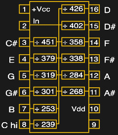
Almost all of the TOGs took an input frequency derived from a 2 MHz crystal oscillator circuit and provided twelve or thirteen square waves of the right pitches by dividing this input frequency by factors from 239 to 478. If we had to implement this in silicon, we’d build up twelve 9-bit counters, all driven by the same 2 MHz master clock, and cause them to reset when the right counts were reached. This should be easy to replicate in firmware on an Arduino, right?
Microcontroller Non-Solutions
The highest “C” on a piano clocks in at 4,186.01 Hz, meaning that we’d have to toggle a pin approximately every 1,911 cycles for an AVR ATmega Arduino clocked at 16 MHz. One pitch would be easy. This might suggest that you could implement this naively in software, keeping track of twelve counter variables and testing in a loop if each should be reset.
while (1) {
    C7_TOGGLE;
        for (volatile uint8_t i=0; i<12; i++){
        if (counts[i] > tops[i]){
            counts[i]=0;
        }
        ++counts[i];
    }
}
But it doesn’t scale. If you implement it this way, the time between counts is simply too long, and you’re unable to define any of the pitches accurately enough that it’s musically useful. The loop above runs around 20 kHz, which is nowhere near fast enough, and all the pitches are out of tune.
An alternative approach would be to let a hardware timer run free, set up a timer variable for each oscillator, and toggle each oscillator when its individual time is reached and then update the GPIO pins.
But because the divided-down oscillators are running at different frequencies, even with only two such oscillators, they will phase in and out. Eventually two transitions will come so close to overlapping that going through the loop takes too much time to service them both, and one will reset late. With twelve oscillators running, the resulting jitter is audible, and it sounds horrible.
These concerns, and a desire to do away with the flip-flop dividers, is what lead Tom [Electric Druid] Wiltshire to build his TOG with twelve PICs, one for each note of the scale. To run in tune together, though, they need to run on the same master clock, and Tom reports problems with the PLL he was using as a master clock. I have aesthetic concerns with using twelve PICs, though I suppose it’s not worse than using twelve synchronous counter ICs for the octave divisions.
Most microcontrollers have onboard hardware timer circuitry that can do exactly what we need, but twelve independent timers is pushing it. An ATmega-powered Arduino has three hardware timers, and one is tied up by the Arduino firmware. If you’re willing to ditch millis(), you could implement three of these oscillators in hardware and probably run a fourth on the CPU. You’d only require three Arduinos for a full octave. We might be getting somewhere.
Overkill, But Plausible
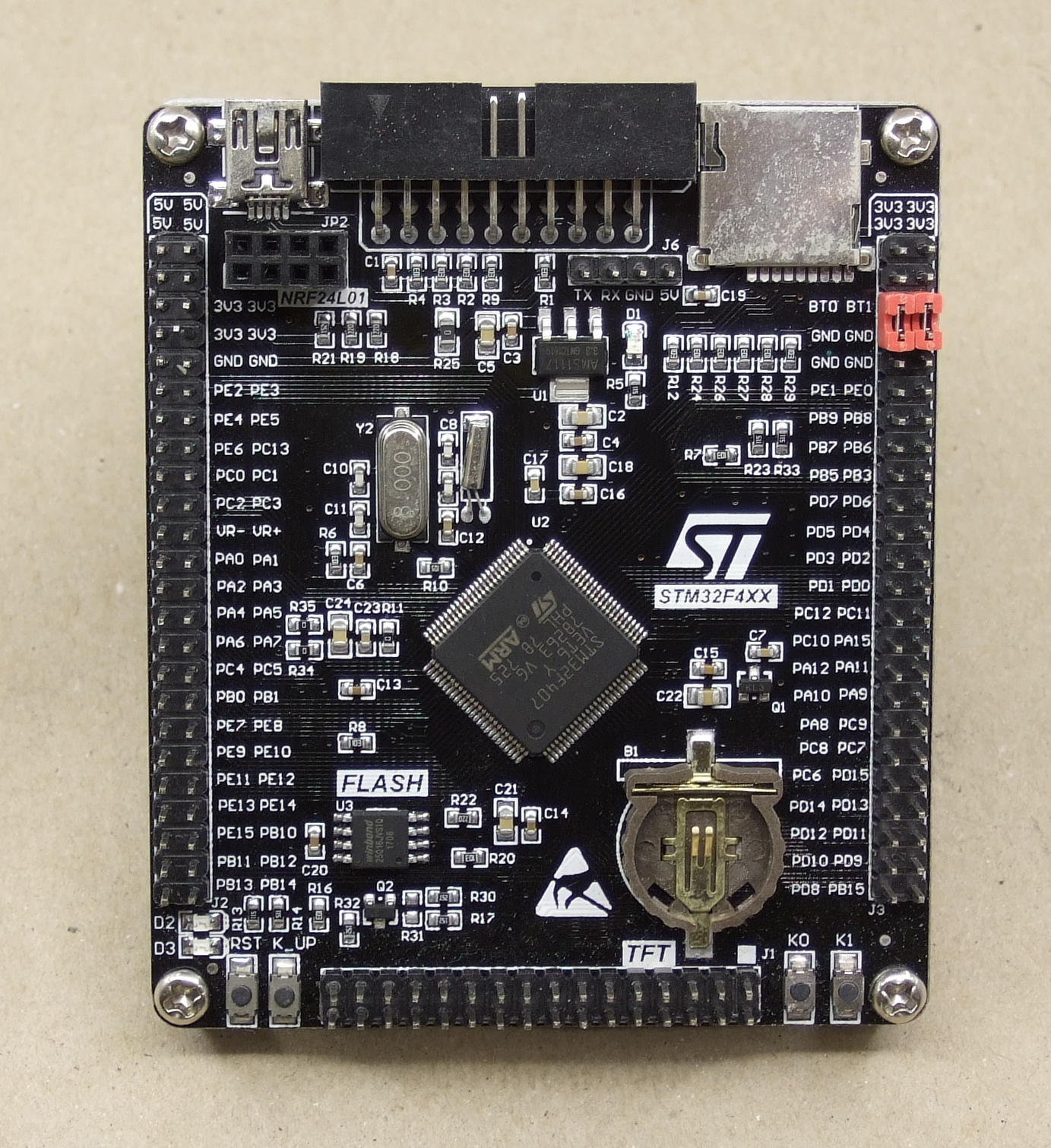 Some fancier microcontrollers have twelve or more hardware timers. I looked around and found that the high-density STM32F407 boards, which are available for not too much from the usual sources, have twelve 16-bit timers. I’m not sure if all of them are available, or operable at once. Still, the all-hardware approach has the advantage of rock-solid timing, and 16-bit resolution on the pitches is an improvement over the old-school TOGs. But throwing a higher-end microcontroller at the job just to leave the 168 MHz CPU completely idle seems somehow wasteful.
A TOG is actually a perfect application for an FPGA. You could implement the divide-down-by-counter design of the original ICs fairly faithfully, and each of the sub-circuits in and FPGA run independently and truly in parallel. Implementing the flip-flops for division would be easy enough as well, and as long as the FPGA has 88 free output pins you could generate all desired pitches in one piece of silicon. That would be pretty sweet.
Your Turn
My gut feeling is that the FPGA solution is the best, although it won’t be DIY-friendly for the majority of organ-repair hobbyists. Everyone knows Arduino, but syncing up three or four of them sounds like trouble. The high-end microcontroller solution should work, but feels wasteful.
What are we missing? Where is the clever hack that will allow twelve independent timers to run in software on a single AVR Arduino? Just for the mental exercise we’re really interested in hearing a working microcontroller solutions. But maybe you have some secret trick to keep a dozen 555 timers in tune? (We’ll believe it when we hear it!) Anyone want to show us how easy the FPGA solution could be? How would you implement a TOG?


Revised my program. Here’s the file header
; AtMEGA328P emulation of a Top Octave Generator (TOG) IC (e.g. MK50242) driven by a 2MHz clock
;
; note frequency(Hz) Output
; C9 8368.2 D2 (PD2)
; B8 7905.1 D3 (PD3)
; A#8 7462.7 D4 (PD4)
; A8 7042.3 D5 (PD5)
; G#8 6644.5 D6 (PD6)
; G8 6269.6 D7 (PD7)
; F#8 5917.2 D14 (PC0)
; F8 5586.6 D15 (PC1)
; E8 5277.0 D16 (PC2)
; D#8 4975.1 D17 (PC3)
; D8 4694.8 D18 (PC4)
; C#8 4434.6 D19 (PC5)
.SET MAKEC8 = 0 ; set this to 0 if C8 is not required, 1 if C8 is required.
; C8 4184.1 D1 (PD1) – derived from C9, not included in the following description
This is a more faithful emulation than proposed elsewhere based on a 1MHz output and producing notes half the frequency.
It can be compiled to do either 12 or 13 notes (MK50240). I found out D0 and D1 are linked in some Arduino boards to serial comms, the 12 note version now avoids those pins. Using D1 was unavoidable for the 13 note version, it is used as TX so already an output, just reassigned. There is the option in the program to compile it with dividers based on the 16MHz clock which are closer to the equal tempered scale for some notes. The output is constrained to producing square waves based on a 2MHz clock so it will appear to jitter but this goes away after being divided down in a string of flipflops.
Also, the divisions are stored in flash and moved to RAM and could be manipulated on the fly to change scales (plenty of room in flash for hundreds of alternate scales). I estimate it would be possible to change the dividers every 2mS so might be able to emulate tremolo effects.
If you are interested, email me at project1@cashin.net
This would clearly make a good interview question for an embedded/hardware position. :-)
In case anyone looks at this, I resurrected this project. There are public domain source and documentation at https://sourceforge.net/projects/top-octave-generator/