Almost every product on the market has been through the hands of an industrial designer at some point in its development. From the phone in your pocket to the car in your driveway or the vacuum in your closet, the way things look and work is the result of a careful design process. Taking a look inside that process, like with this wireless phone charger concept, is fascinating and can yield really valuable design insights.
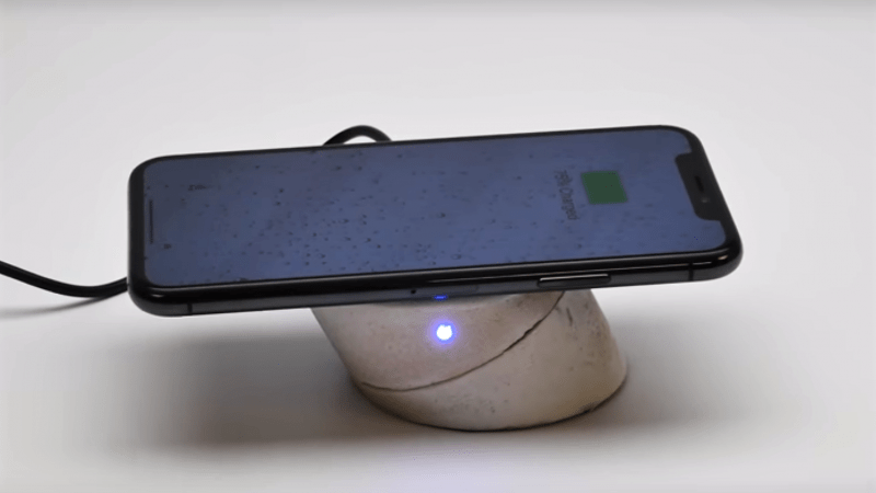
We’ve featured lots of [Eric Strebel]’s work before, mainly for the great fabrication tips and tricks he offers, like how to get a fine painted finish or the many uses of Bondo. But this time around, he walks us through a condensed version of his design process for a wireless phone charger and stand. His client had specific requirements, like being able to have the phone held up in landscape or portrait mode, so he started with pen and paper and sketched some ideas. A swiveling cylinder seemed to fit the bill, and after a quick mockup in PVC pipe, he started work on a full-size prototype in urethane foam. There are some great fabrication tips in the video below, mainly centered on dealing with not owning a lathe.
The thing for us with all of [Eric]’s videos, but especially this one, is seeing the design process laid out, from beginning to (almost) the end. He sure makes industrial design look like a cool gig, one that would appeal to the Jacks- and Jills-of-all-trades who hang out around here.


He has a 3D printer, since he says he printed the part that holds the PCB, so why didn’t he print the whole thing? That seems far easier, way less messy in the shop, and much cheaper because it’s less labor intensive.
Also, isn’t it common to include magnets to hold the phone? I didn’t see those.
Exactly my thoughts
@Sparkygsx & @Jake Lee he explains his choice on the second video: https://www.youtube.com/watch?v=N61PU2ZkYtA&t=513
Exactly my thoughts, too.
If you check the next video of the process, he explains (8:33) that at this stage of the process you’d go for many iterations of design variations, at this point a computer is too limiting and he thinks it’s quicker/faster to make stuff out of foam.
In an other video (advanced bondo, ~4:00), he explains that the purpose of its channel is to share and preserve ‘old’ technics for model making.
It still doesn’t make much sense to me; if the computer is “way to limiting”, you need to improve your CAD skills. Going through iterations is as simple and changing the CAD model and sending it to you printer, and you do something else while the printer is doing it’s thing. You can do a lot a things that you can’t do with his manual method; you can’t turn an ellipse in a lathe, for example. Also, you can make the hinge snap together, put in endstops so the USB connector can be in the bottom part, and not pull the whole thing over, etc.
3D printed would be much sturdier and you can easily make several units if needed. He even specifically says to truly hates PU foam. Does not compute.
Excellent points. I doubt many large firms would wait for Joe Designer to finish his foam lathe prototypes for long before they just hired the next adequate CAD designer from an engineering school.
Don’t let nostalgia cloud your judgment.
This is certainly IF it is true that the mechanical skills of clicking in a CAD program are the job of an industrial designer. If it turns out to not be a mechanical job, but actually a creative job, then the speed of tool use might not be relevant.
There are a significant number of connections in the brain between general spacial mapping and vision. Some people are better at picturing how things fit together when they can see the shapes in abstract wire frame, but other people are better at picturing it when looking at one of the parts in actual 3d, with real depth perception. Obviously the people with stronger spacial skills will prefer the computer, but spacial skills are merely an important ancillary skill here; the creative skills need to lead this activity, and any set of ancillary skills that lead to success might be good enough for a person with the sufficient primary skill.
Engineering schools don’t tend to even value the sort of creative skill that determines success at this task, so just looking for a degree and some computer skills is going to lead to ugly boxes that nobody buys, but that are documented as to exactly how much force they can withstand in every direction. The quality of results is exactly why a company would hire an independent designer! They probably already have good engineers who can’t do it well.
Have to disagree. Sometimes CAD wins, sometimes ‘organic’ modelling wins. I’ve seen both work, and in the right place, each can be a clear winner with the other trailing in the dust.
>>…..you can’t turn an ellipse in a lathe,….
That’s not strictly true. There’s all sorts of eccentric turning tricks you can use. The restrictions are the rigidity of your lathe and how oval is oval enough. At least for metal. Almost any lathe can turn ovals in wood without trouble, aside from the correct jigs and mounts.
I’m speaking from my experience as an Industrial Designer here (as well as a heavily experienced rapid prototyping lab technician, prior). It’s much faster to use foam (or some prefer things like clay). Why? Because the whole point of the process is to find what you want the final result to be with what visual language, function, and ergonomics work best.
Iterations don’t necessarily mean that they are near-clones of one another with one minor change appended each time. Foam can be carved away using a surform shaver in a matter of minutes and produce iterations that are as different as a cube, cylinder, and sphere.
Part of the problem here is that Eric is using slow processes with lots of unusual jigs that are all time consuming and that’s just not very typical. A lot of what he’s doing is to demonstrate a technique. He even states that he’s using a process that isn’t typical for him. Even at the end of it all he says he’s going to CAD in the next step so he can do things like you’re saying he should do. The side you’re not thinking about is that he needed the information from this step to ensure that his CAD model didn’t have inherently weak visual language, function, or ergonomics as well as dimensions.
I could go on, but I digress.
“mainly centered on dealing with not owning a lathe” – the way to do that is buy a lathe…
“We’ve featured lots of [Eric Strebel]’s work before”
Yeah, no shit. This is the second time in a week. But hey, I’m willing to let it slide since he shows us how to come up with a completely original design.
Skip to 7:08 for the robot caviar… mmm…
Thanks and real professional from concept sketch to first working prototype, no sweat. It is a formal way to do a decent job.