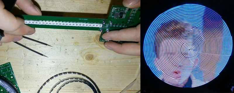
When [Im-pro] wants a display, he wants it to spin. So he built a persistence of vision (POV) display capable of showing a 12-bit color image of 131 x 131 pixels at 16 frames per second. You can see a video about the project below, but don’t worry, you can view it on your normal monitor.
The project starts with a Java-based screen capture on a PC. Data goes to the display wirelessly to an ESP8266. However, the actual display drive is done by an FPGA that drives the motor, reads a hall effect index sensor, and lights the LEDs.
Perhaps the most interesting part of the project is the FPGA-based mapping of the rectangular coordinates of the incoming video to the polar coordinates required by the display. There are 4 arms of LEDs or “wings” and a 3D printed structure that is all included in the post.
The FPGA is a Cmod S6 which is a breakout board for a Xilinx Spartan 6 with more than enough horsepower to handle the workload. There are also custom PCBs involved, so when you think about it, it is a fairly wide-ranging project. Java software, ESP8266 software, FPGA configurations, a 3D-printed design, and PCB layouts. If you want something simple to tackle that has a bit of everything in it, this might be your next project.
Most of the POV displays we see don’t have this kind of color-depth and resolution. We’ve seen displays built around fans. Our favorite, though, is the dog speedometer.


Having recently bought a VR headset, I’m asking myself whether it would be possible to create a virtual POV display inside it.
Do we need a new video format for POV displays, so we can watch Youtube videos on them?
Decades ago, there was a persistance of vision headset made by Reflection Technologies. It consisted of an oscillating mirror and a vertical strip of tiny LEDs.
Why do you think we’ve all been collecting propellor beanies all these years? Just 3D print a suitable LED attachment and put a motor on top your head and Bob’s your uncle.
Wasn’t that the heart of Nintendo’s Virtual Boy?
Yes.
Virtual POV display? As in you see a spinning object displaying an image in a game engine?
Considering POV happens in our eyes, virtualization might be either tricky or purposeless. I suppose you could say that any display (HMD included) is a POV display, in that it depends on your persistence of vision to make the image look steady and constant while it’s actually refreshing the screen dozens to hundreds of times per second.
@[Al Williams]
So for the metrics of FPGA capacity we have –
Gates – Logical Gates
Macros – Macro Cells
LEs – Logic Elements
LUTs – Look Up Tables
and now –
Horse Power!
This would not be concerning except that Horse Power probably makes as much sense as the other metrics.
If we’re talking about metrics that make sense, can’t we just use good ol’ Watts? Who is using horses for power these days?? ;)
Watching him place all the parts in Eagle was painful – won’t somebody please teach him about Eagle’s scripting tools?
Won’t someone teach me about Eagle’s scripting tools?
:-)
Ok, I’m sure there are _far_ better tutorials out there for anyone that can Google, but…
Eagle will quite happily take text commands like this:
move led1 (0.5 0.5)
Surprisingly enough, that command will MOVE a component with the reference designator of led1 to the coordinates specified (no units here, inherited from settings in the GUI tool) You can type them directly into the editor if you like, but this becomes much more powerful….
With a little bit of creativity and a sprinkling of math, I use Excel to generate a column of such lines with the reference designator incremented and the coordinates mathematically generated. One command per line. Most any programming language could be coerced to do the same – use any tool you find convenient as long as you end up with something like this:
move led1 (0.5 0.5)
move led2 (0.5 0.65)
move led3 (0.5 0.8)
move led4 (0.5 0.95)
move led5 (0.5 1.1)
Save that as a plain text file with an scr extension.
In Eagle’s board editor, under File, there is a Script menu item. Select it, point it at the file you created a couple steps ago and watch all your parts move around.
Most anything you can do with the pointy-clicky interface can be done with a text command as well. The above snippet is from a board I laid out that was a 48×48 grid of 0604 LEDs – hand placing and routing 2304 LEDs would take hours or days. Took about an hour to write and run the scripts to place them, and most of the routing.
I’ve also used this when I needed to place a 100+ LEDs in a mathematically described curve. It’s also particularly useful for making package layouts. You can place and name all the pin locations regardless of the interface grid settings.
The interlace scanning was a nice twist (even is borrowed from television 70 years ago).
Al, when you say this: “If you want something simple to tackle that has a bit of everything in it, this might be your next project.”, I presume you are just joking.
;-)
Funnyman.