 When something needs improving, most hacks often make a small tweak to address a problem without changing how things really work. Other hacks go a level deeper, and that’s what [Felix Rusu] did with his 3D printed magnetic holders. Originally designed to address a shortcoming with the PCB holders in his LE40V desktop pick-and-place machine, they turned out to be useful for other applications as well, and easily modified to use whatever size magnets happen to be handy.
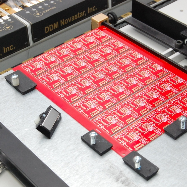
The problem [Felix] had with the PCB holders on his pick-and-place was that they hold the board suspended in midair by gripping the sides. The board is held securely, but the high density of parts on panelized PCB designs leads to vibrations in the suspended board as the pick-and-place head goes to work. Things are even worse when the board is v-scored for the purpose of easily snapping apart the smaller boards later; they sometimes break along the score lines due to the stress.
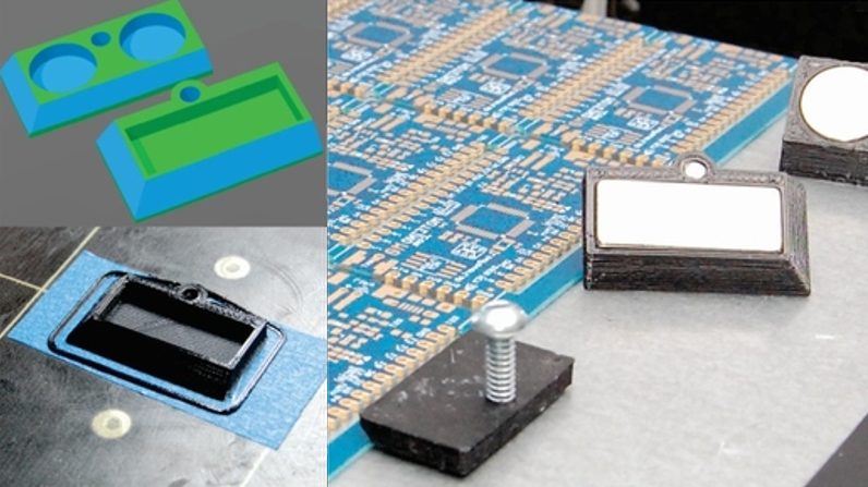
Most people would solve this problem by putting a spacer underneath the board to stabilize things, but [Felix] decided to go a level deeper and change the mounting system altogether with a simple mod. The boards now lie on a flat metal plate, and his magnetic holders are simple to make and easily do the job of holding any size PCB secure. As a bonus, it turns out that the holders also do a passable job of holding work materials down on a laser cutter’s honeycomb table. A video overview is embedded below, and the design files are available on Thingiverse.
The beveled edges and screw for a handle are nice, but back before 3D printers were common we briefly saw another way to make magnetic holders: plop down the magnet, gob on some oven-curable modeling clay, mold it as needed, then bake in the oven. Sugru (or its home-made alternative, Oogoo) might also do the trick.


V scoring is not for snapping pcbs apart and doing so can damage components and or solder joints.
Dear Charles, perhaps you would like to enlighten us with the real function of V scoring?
But perhaps I should save you the trouble. The cut in the shape of the letter V is nothing more then a double sided groove, a weakened point of the PCB that allows you to separate the PCB. But you must not see this groove as a weak point from where you can snap the PCB in half, because if you do that you’ll create stress on the PCB (and it’s soldered components) and eventually damage something on the board. And that your PCB’s are working when tested, doesn’t mean that there are no cracked components due to the bending forces, some fault may show themselves over time (caused by temperature cycles, extracting/expanding). Instead you must use the V groove in combination with a proper separator tool for instance:
http://www.pcbaseparator.com/sell-1836329-pcb-depanelizer-machine-for-v-scored-pcb-board-ysvc-1.html
That way the PCB is effortlessly split without applying bending forces in the horizontal plane of the PCB.
If you do not have such a tool, then you should order your PCB with mousebites.Or use a knife to split the PCB’s but that is not without danger as the knife will get dull very fast and a dull knife is an dangerous knife!
Regarding the project, I was slightly surprised that there wasn’t a proper PCB fastening method supplied with the machine. They could at least have added a bag of fridge magnets with the machines company logo?
V scoring is to create a beveled edge for card edge connectors. The bevel separates the socket connectors gently as a flat edge would jam and damage the connector.
Tell that to all the people that use V-scoring for panelization. At this point, V-scoring is probably used, at least, as much for panelization as it is for card edge connectors.
Typically that is not called a v-score.. google “v-scoring edge connector” and look how nothing really matches up with this. Sure, there is probably a machine -similar- to a v-score machine that makes those bevels on card edge connectors, but a v-score is deep and designed to facilitate board break-off.
You are using the wrong terminology and that will net you some crappy edge-connectors in the future if you tell a PCB-house “v-score here” and they don’t catch your mistake first. Edge connectors are special and need to be called-out, include things like a bevel degree and other mechanical dimensions. A v-score is usually just represented as a single line or occasionally a width if you bother with kerf.
3D printed? Really? Those trinkets could be done in like 30 minutes with angle grinder.
It does seem like 3D printing is being used for a lot of things where more traditional fabrication methods would be both easier and faster, and would also produce a superior product. Is that because it’s still “new and shiny”? Or is it because 3D printers tend to be owned by electronics types who aren’t familiar with other methods and tools?
3D printer is the jack of all trades. Not the best for each application, but one machine that will do the job for many cases. Not everyone have a workshop in their houses or at work.
Thirty minutes of active effort that results in something with identical performance.
I’d rather throw a model onto the printer and do something else with my time.
I did something similar, but just with hot melt. Took 2 mintues for a dozen.
I place the magnet as he does in the beginning and just hotmelt under and over. Once it cools, I pull it off the board and table, but leave the magnet inside. The ‘sticky’ hotmelt material combined with any surface features gives amazing hold compared to harder plastic.
Heh first thing I thought was I could easily do that with wood! Couple mins with a drop saw and a suitable drill bit to make the cutouts to glue in the magnets.
Just grind a beveled edge on any magnet that’s thicker than the PCB. Or, use multiple magnets to secure a triangle-shaped wooden shim. Even easier, place one magnet jammed against the edge of the PCB and a second magnet stacked on top to hold the board down.
Otherwise, excellent practice for making stuff with a 3D printer. Thanks for sharing your work.
I guess this works for single-side PCBs, but what if you need to populate both sides? For a PCB with the parts on the bottom already soldered, you could probably laser-cut a support plate out of acrylic or even wood, with holes where the parts go. Other than that, I wouldn’t know how you could hold the panel other then just by the edges.
That’s what I did for my double-sided boards – lasercut a frame out of 2mm acrylic and put boards onto it. As for other way to hold the panel – double-sided tape works, though you’ll want to make sure you can remove the board from the table without shaking the components off.
Interesting. We too have a PnP, but I’m not sure if the table is magnetic… Time to check – these sure would help, as opposed to double-sided tape we usually use!