There’s something powerful about reliving the experience of using a game console from our personal good old days, especially the tactile memories stored up from hundreds of hours handling a chintzy joystick or the sound and feel of inserting a game cartridge. Emulators have their place, but they fall far short of period-correct hardware in the nostalgia department.
That’s not to say that the retro gear can’t use a little help in terms of usability, which is why [Scott M. Baker] built this Raspberry Pi multi-cartridge for his Atari 5200. The idea is to maintain the experience of the cartridge interface without having to keep stacks of cartridges around for all the games he wants to play. [Scott] leveraged the approach he used when he built a virtual floppy drive for a homebrew PC/XT: dual-port memory. The IDT7007 is a 32k chip that lives between the Atari 5200 and a Raspberry Pi Zero and can be addressed by both systems; the Pi to write ROM images to the memory, and the console to read them. He had to deal with some fussy details like chip select logic and dealing with the cartridge interlock signals, not to mention the difference in voltage between the memory chip’s logic levels and that of the Pi. Retro game-play occupies the first part of the video below; skip to 6:45 for build details.
The one quibble we have is trying to jam everything into an old cartridge. It’s critical to replicating the tactile experience, and while we don’t think we’d have gone so far as to injection mold a custom cartridge to house everything without any protrusions, we might have 3D-printed a custom cartridge instead. In the end it doesn’t detract much from the finished project, though, and we appreciate the mix of old and new tech.


Oh wow, the Atari 5200 homebrew scene is going to be all a twitter about this! ;P
AtariMax for 5200 has been around for a while and can load game via SD card.
Neat!
Only thing is the SRAM used costs about $60AUD new vs $6 for some single port SRAM
Since the Pi and the Atari don’t need access to the RAM at the same time you can just use a couple of buffers to disconnect the RAM from the atari while programming it which is what I’ve done in the past to build a ROM Emulator for my homebrew 6502
Here’s a schematic of mine to explain what I mean, the pin headers go to my raspberry pi, when programming is done I high-z the raspberry pi’s outputs. the ROM CS signal is OR’ed with the buffer enable so that the programmer can disable the buffers while programming
https://i.imgur.com/UTi3hWj.png
Link is broken.
Works fine for me, as of right now.
Seems to alternate between broken & working for me but this link should work
https://imgur.com/UTi3hWj
JP1 goes to the ROM socket, JP2&3 Go to my raspberry pi
everything looks like a nail strikes again, Scott used IDT7130 for Pee floppy interface, so now everything needs dual ported Sram :)
i love to do this with snes
https://www.mortoffgames.com/super-nintendo-/homebrew-equiptment/boards/simple-save-pcb
Use Bills common method to interface with memory don’t know about avoiding RARE chip special things and the FX2 chip like in STARFOX
AFAICR, the old, back-in-the-day SNES copiers (using floppy disks and a couple of MB expensive RAM) had a bypass socket, into which you would plug a real cartridge. It passed through the connection to the security chip, so the real cart’s security chip opened up the console, while the copier provided the game data.
This also worked for FX-chip etc games. You just need any old cart with the particular chip you need. Presumably the extra chip responds to it’s address range when it’s asked for.
It only worked for the DSP-1 coprocessor. Others placed the ROM behind the coprocessor as a copy-protection mechanism.
Using dual-ported VRAM is another option. The main differences are that the video data port is serial and the address bus must be shared. But since access is by whole rows of RAM, you don’t need to use the address bus so much..
Do they even make that any more? It’s a bit 1994-ish.
Very nice work,
Truly a piece of art.
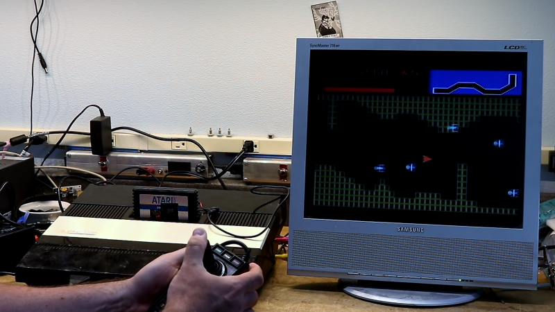
I have that monitor! Well… Mom does, I gave it to her since I have plenty of my own. She’s been using it for… dunno, over a decade possibly. The audio connector is getting a little questionable now. By the way, inputs are VGA, composite, and coax — it’s also a TV!
Samsung SyncMaster 510MP, if anyone cares. It’s only XGA resolution (1024×768), being a 15″ non-widescreen LCD, but Mom’s happy with it, so…
There’s a 17″ version, too, the 710MP. A friend of mine has that one… dunno the res but almost certainly 1280×1024… most 17″ non-widescreen monitors are that.
5:4 you say? Heresy!
I had several monitors with resolution 1280×1024 with rectangular pixels, so 5:4 as well. It´s not bad. I even found a problem when I moved to widescreen monitor – I have to place the taskbar (or whatever you have in your system of choice) on the vertical edge of the screen, otherwise a significant portion of the display is not used usefully.
MOS 6502C works with only 1.79MHz clock. Isn’t cheaper to simulate ROM chip with high end MCU? Modern Cortex-M MCU should be able to handle requests with such clock rate.
I think he has it so that the game image is written to the dual-ported memory and to the console appears as a complete cartridge (as in the pi writes it once and is done, no further intervention).
I like this idea as it means another mcu doesn’t have to act as a fifo and forever fetch data in response to address as a buffer. I assume that this would make the programming easier for the rpi?
No, it wouldn’t. However MCU with 64-256 kilobytes of integrated SRAM costs from 5 to 10 times less than this ridiculously expensive dual port SRAM chip. As long as you don’t need to achieve tens of MHz clocks any modern MCU can simulate SRAM chip just with GPIO and EXTI. The way cartridge image loaded into this MCU may differ. For example you can use SPI/I2C/UART or even something like ESP8266 (don’t try to combine two tasks to single core) to load image, so even schematics will be simpler than solution from this article.
The Raspberry Pi’s standard Linux isn’t realtime, it can’t guarantee adequate response times to I/O events. And going through the whole OS to access the pins is likely to be much slower than doing it in machine code. Which you generally don’t do with a Pi, much of the hardware info isn’t available, and if you went for the bare metal you’d lose most of the advantages having a Linux board brings.
A much simpler way would just to use single-port SRAM. There’s no need for both sides to access it at the same time. Maybe a bit of logic for the SRAM’s /CE line , and tristate the Pi’s bus once it’s done it’s job. The 5200 can surely cope with garbage on the data bus during setup, you’d just reset the thing once the game’s loaded in.
I think his point is a $5 pic32mx274 runs at 80Mhz…. and has 256MB of flash/64k of ram…
And all it has to do is loop and copy data from ram to an IO port, and open a menu on reset. One or two of these should handle any level conversion… https://www.digikey.com/product-detail/en/texas-instruments/TXB0108PWR/296-21527-1-ND/1305700
So in all… a $5mcu, $2 level converter , $1 mems OSC, 1in oled $2, 4 buttons, $1 SD card card slot, $15 on the PCB $2 worth of passives and a programming header… that gets you to about $25 total give or take.
If that is actually fast enough to work though is the real question… it should be. You could probably even implement bank switching.
For a couple more quid, add a SRAM chip so at least you don’t have the hell of trying to emulate one in code. Using an MCU would be a pain in the arse to debug, with a SRAM everything’s modular and essentially doing the job the gods intended it to. You wouldn’t have to worry about instruction timing, writing stuff in asm, and whatever other stuff. You’d be able to start off with a simple working system, then add stuff a step at a time from there logically.
The extra couple of quid could probably be absorbed in being able to use any old cheap MCU. If you do it Arduino, you have USB uploads built-in no bother, set it to an emulated serial port.