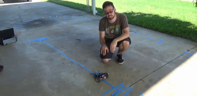
Line-following robots are a great intro to robotics in general, since the materials and skills needed to build a good one aren’t too advanced. It turns out that line-following robots are more than just a learning tool, too. They’re pretty useful in industry, but most of them don’t follow visible marked lines. Some, like this inductive guided robot from [Randall] make use of wires to determine their paths.
Some of the benefits of inductive guidance over physical lines are that the wires can be hidden in floors, so if something like an automated forklift is using them at a warehouse there will be less trip hazard and less maintenance of the guides. They also support multiple paths, so no complicated track switching has to take place. [Randall]’s robot is a small demonstration of a larger system he built as a technician for an autonomous guided vehicle system. His video goes into the details of how they work, more of their advantages and disadvantages, and a few other things.
While inductive guided robots have been used for decades now, they’re starting to be replaced by robots with local positioning systems and computer vision. We’ve recently seen robots that are built to utilize these forms of navigation as well.


That is a very good video! The only criticism is it doesn’t say much about the wire itself and what frequency and current it runs at. Maybe somebody here knows more about it? ????
Check out this kit from Robot shop … Only $9 …. https://www.robotshop.com/en/robotshop-perimeter-wire-generator-sensor-soldering-kit.html
Thanks! ????????
I recommend also checking the guide by the designer here: https://www.robotshop.com/blog/en/diy-perimeter-wire-generator-sensor-21302
I received a kit today, works ok although I suspect the band pass filter capacitors need to be better tolerance than the standard 10%. I’m considering replacing them with 1% and see if that evens out the response from each channel.
I kept a note to change the LC circuit 22nF capacitors with better tolerance ratings such as ±1% instead of ±10%. Thank you for the feedback :)
I kept a note to change the 22nF band pass filter capacitors with ones that have better tolerance ratings such as 1% instead of 10%. Thank you for the feedback :)
why do you “shy away from Arduino”?
I think the wire is just a (metallic) wire. The rover will generate some electrical or magnetic field and measure the energy absorbed by the wire, or may have two fixed magnets and measure the disperded flux when the metallic wire is near to one of such magnets. Also, if the magnet is strong enough, the device can measure the force applied to the flexible support that holds the strong magnet. I don’t know, it’s just an opinion, but I would use one of such approaches if going to create my own prototype. Also I know there are studies for “smart cities” with similar approach to make vehicles able to run without a driver in the city (or run with a driver that is looking at his smartphone’s screen, writing messages to friends). If the wire is emitting a signal (for example the classic 50Hz of mains power) the detector circuit will be very easy to build, making a difference amplifier for two magnetic heads (solenoids) and then discriminate the position of the wire respect to the sensors. Anyway, I will prefere a solution with a simple metallic wire without any emission. It’s simpler to realize. I also suggest to not use a single long wire, but small pieces cut at a length thay can resonate at a certain frequency (like some cheap tags used as anti-robbery in supermarkets). Using this way the rover can emit a specific frequency and measure the feedback more efficiently.
You do not want to design a system that just detects the wire with no signal driven on the wire. Systems like this are often used on concrete floors that are filled with rebar and wire mesh and possibly metal pipes that would completely confuse such a system.
I think that will be not too difficult to discriminate betrween our guide wire (with no signals) and various pipes and electric wires in the floor, however, if you read my post up to the end, I suggested to use small wires cut at certain length to make easier to measure the resonance at a specific frequency.
I will add that I can easily build a self driven rover using the smart tags that are applied (self-adhesive) to the rubbish-bags in my city. Such smart tags are readable and writeable and can contain some bytes of data (they works at near 1GHz frequency). So, you can easily detect that there is a tag and also read information about your position and the next operation to do. For example: “maintain the direction and the speed”, “decrease the speed”, “prepare to turn on the right” etcetera. Also, if this system is in a warehouse, you can write on the “floor-embedded tags” other information about the area of the warehouse are you traversing. I think that this way for automatic self driven vehicles will be more accurate and easy to realize than a frequency driven wire, but (as I said in my previous post) these are just opinions.
Just another idea: make a matrix, not a single line. Use a smart tag for each 1 squared meter area and write on each of them the information about its absolute position in the map. Using this way, you can instruct your vehicle to make any route and reach any point in the warehouse, even if the vehicle has to change its route for an obstacle (variable path is a huge improvement respect to single, fixed path). This is VERY easy to realize and very cheap. Consider that one tag costs about 5 cents; you can cover a 100 squared meters area spending just 5 dollars. The reader mounted on the vehicle is also very cheap and easy to connect to a microcontroller. Add an electronic compass and you can build you smart autonomous (in-warehouse) vehicle for less than 20 dollars (excluding the mechanics!). I don’t have a warehouse where experimenting such solution, but I’m pretty sure it will work without any problem. As additional tool, you can add some wifi access points (small 2 dollars units) just to help finding the abolute position of the vehicle using the RSSI value received from the on-board wifi station.
Can you please share your email id I have some questions please
“Line-following robots are a great intro to robotics in general, since the materials and skills needed to build a good one aren’t too advanced.”
It’s one of the exercises in LogicBots.
Wire guidance systems are often used in warehouses to guide autonomous package moving robots, and are even used with forklifts driven by humans, when driving in tight warehouse isles where the driver can’t be trusted to not bang into shelves. The system works by cutting a slot in the concrete floor into which you place the wire, then seal up the crack with epoxy or something to protect it from harm. The wire is driven with a signal, but it’s been many years since I worked on systems like this so I don’t remember the current or frequency. The robot or forklift is fitted with two antennas, one on each side of the center line, and the system steers to keep the signal received by the antennas equal.
See above. A bit more sophisticated to prevent line-wiggle, and to deal with right-angle turns.
Typical frequency is roughly in the 10 kHz region (different frequencies are often used to differentiate guide wires).
As you say, these are often used for steering control on manual vehicles where even an experienced driver would have trouble keeping centered in a very narrow aisle (think only 6 inches or so on either side of the vehicle) without hitting the racking on either side. Wire guidance in VNAs has been pretty much standard for a few decades.
I’m envisioning railway track style systems where the lines can be switched by changing frequencies to guide and prioritise robots moving around a busy factory.
I wonder if conductive paint would work here/be economical? The generally rough treatment of warehouse floors has me feeling dubious about that, but maybe it could be good for a place that was frequently reconfiguring the floor plan (and thus cannot use embedded-wire line following)…