If you have even the slightest interest in microwave electronics and radar, you’re in for a treat. The Signal Path is back with another video, and this one covers the internals of a simple 24-GHz radar module along with some experiments that we found fascinating.
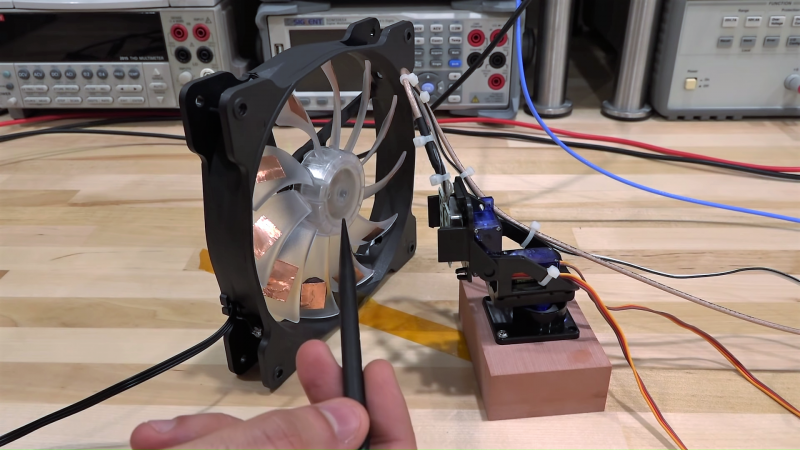
The radar module that [Shahriar] works with in the video below is a CDM324 that can be picked up for a couple of bucks from the usual sources. As such it contains a lot of lessons in value engineering and designing to a price point, and the teardown reveals that it contains but a single active device. [Shahriar] walks us through the layout of the circuit, pointing out such fascinating bits as capacitors with no dielectric, butterfly stubs acting as bias tees, and a rat-race coupler that’s used as a mixer. The flip side of the PCB has two arrays of beam-forming patch antennas, one for transmit and one for receive. After a few simple tests to show that the center frequency of the module is highly variable, he does a neat test using gimbals made of servos to sweep the signal across azimuth and elevation while pointing at a receiving horn antenna. This shows the asymmetrical nature of the beam-forming array. He finishes up by measuring the speed of a computer fan using the module, which has some interesting possibilities in data security as well as a few practical applications.
Even though [Shahriar]’s video tend to the longish side, he makes every second count by packing in a lot of material. He also makes complex topics very approachable, like what’s inside a million-dollar oscilloscope or diagnosing a wonky 14-GHz spectrum analyzer.


WOW
I think you did a great job.
I learned a lot.
Thanks
You are welcome.
From my experience with these radar modules, the best part is hooking up the IF signal to an audio amplifier and listening to all the movements in the room :)
Roll your own → https://github.com/turingbirds/motionsensor
(Yes, I should make a demo video, with sound…)
Indeed archels, please do make a video with sound as I don’t have the opportunity in near future to build your project though thanks for the link to the files. A video would be a great example and likely also entertaining too, heck could even make a form of theremin type music entertainment too for for all including the ‘experienced’ children in the family ;-)
I imagine some bipedal robot wandering around with such audio from it as it senses its environment ostensibly so blind people in the area can hear it moving around and maybe even in some arena sports game with blindfolded players eg football/soccer. Reminds me of potential for some dystopic future along the lines of “Day of the Triffids” sci-fi story or this first movie attempt, not quite a classic but impressive for kids of the era it was released.
https://www.imdb.com/title/tt0055894
This is cool, but I want an inexpensive project with radar ranging not Doppler, we can add direction track/scan with a stepper and directional antenna.
Maybe a band passed FL2K-SDR TX and RTL-SDR RX?
Dream would be phased array aiming.
Probably needs more analog in the rx/tx loop for the short return times vs granular RTL-SDR sampling rates though, I simply don’t know enough beyond simple college o-scope radar demonstrations.
And sorry for wishlisting and OTing so high in the comments, this was some great DIYing and analysis.
phased array = $$$$$$$, no way around it, at least not above 5GHz
http://www.ti.com/tool/IWR1443BOOST – $300 76 GHz phased array
Excellent early-morning entertainment to digest with my cornflakes !
Hmm, I wonder how one might offer some data transmission options and of more than the ordinary types at the same time whilst doing that radar thang ;-)
Without a PLL, it would be difficult to get anything reliably.
After watching this – which was VERY educational – I can appreciate how extremely high frequency RF design is a far different discipline than anything I deal with day to day. I’m sitting here looking at a PCB design for some digital circuits and switch mode power supplies at work and feeling very relieved that my PCB will have zero concern that the trace lengths and shapes will NOT have a measurable impact on the signals. That and my relatively inexpensive 500Mhz scope is MORE than adequate to debug any problems!!