
Last time on Circuit VR, we looked at creating a very simple common emitter amplifier, but we didn’t talk about how to select the capacitor values, or much about why we wanted them. We are going to look at that this time, as well as how to use a second transistor in an emitter follower (or common collector) configuration to stiffen the amplifier’s ability to drive an output load.
Several readers wrote to point out that I’d pushed the Ic value a little high for a 2N2222. As it turns out, at least one of the calculations in the comments was a bit high. However, I’ve updated the post at the end to explore what was in the comments, and talk a bit more about how you compute power dissipation with or without LTSpice. If you read that post, you might want to jump back and pick up the update.
Back to Our Program
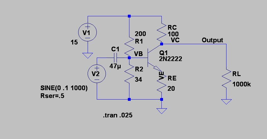
As a reminder, the LT Spice circuit we started with appears below. You can download that file and others on GitHub.
Output Z
Last time, we went over the design equations and even looked at a spreadsheet for figuring out the values. That spreadsheet assumed you wanted to pick a few items including the normal collector current for the device. In some cases, though, your driving design goal will be a certain output impedance. In that case, pick RC accordingly, and go through the same steps but you’ll compute Ic instead of selecting it and skip step 4. You can use this same procedure when the actual load you are driving is the collector resistor, which isn’t uncommon.
It is easy to see that RC is the output impedance if you do a little logic. Remember, this amplifier inverts. So Q1 is as close to off as it is going to get when the input signal is large. Assume Q1 turned all the way off. What would the output circuit look like then? A voltage divider made up of RC and RL. Like any voltage divider, the maximum power in RL is going to occur when RL=RC. If you have more of an engineering mindset, you can think of it as the amplifier’s Thevenin equivalent is a voltage source with RC as the resistor. Or, if you are more graphical, think of a voltage divider with a 10V input and a 100 ohm “top” resistor (R1). If you try values for the bottom resistor (R2) ranging from 1 to 200, it looks like this:
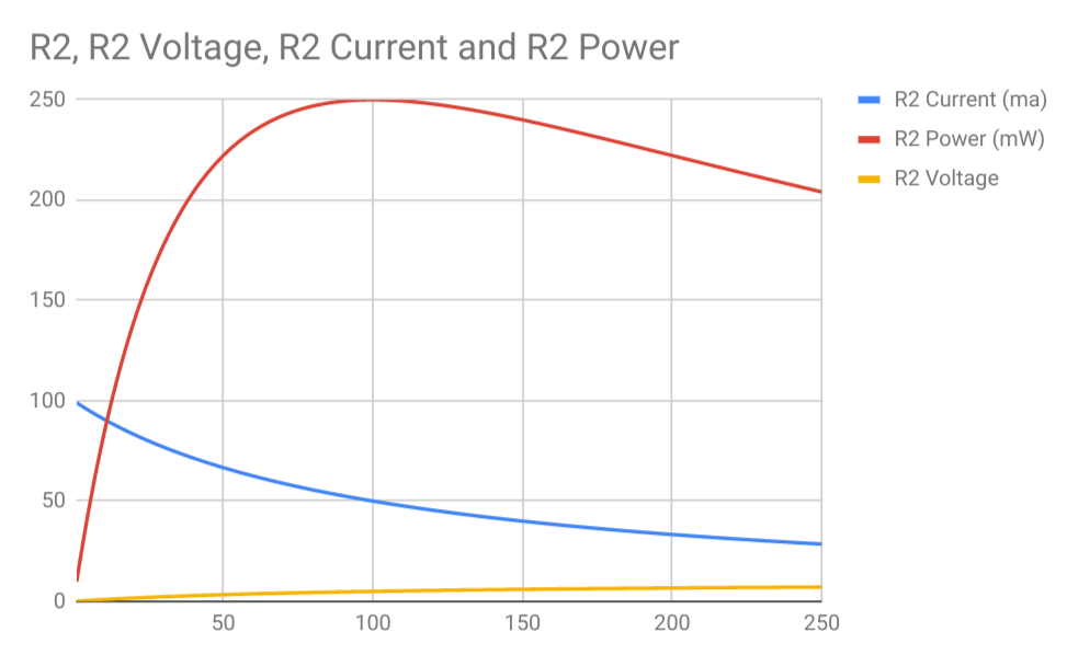
The voltage in R2 keeps going up, but the current goes down. When R2 is 100 ohms, the power maxes out at about 250 mW. This is why you try to match, say, a transmitter with an antenna or speakers with an amplifier.
You might want to control input impedance as well. For the input impedance case, you would have to control the values of Re, R1, and R2 which is quite a bit harder without setting up a lot of simultaneous equations or just iterating. It also will depend on beta, which is notoriously unreliable. If the product of Re and beta is a large number, you can approximate it as R1 and R2 in parallel, and that’s often good enough.
Note that in the above circuit example I just put a large resistor in as the load so it didn’t affect things much. But what if that resistor had been a 16-ohm speaker, perhaps?
Back to Capacitors
So why are capacitors important? Because the transistor needs a very specific set of DC voltages on its terminals and connecting an input or output to it is going to perturb that. However, we can isolate the circuit from any DC effects using a capacitor on the input and the output. That means we can’t amplify very low-frequency signals well — the capacitors will act like large resistors. But at higher frequencies, it won’t be any problem. You can see that in the simulation where some capacitors guard the inputs and the outputs.
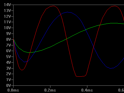
If you want to see the effect in a less distracting way, check out this simulation. Here an input signal is riding a DC level. A voltage divider sets another DC level. With a capacitor between them, the circuit essentially shifts the input to a new DC level, like this:
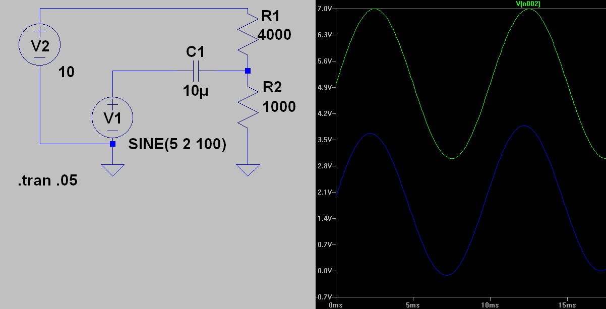
The reactance of the capacitor, of course, depends on the frequency, according to 1/(2*π*f*C). That means the higher the capacitance, the lower the reactance at a given frequency. In this case, the 100 Hz signal sees the 10 uF capacitor as about 160 ohms of reactance. At 47uF, that drops to about 34 ohms. At 1 kHz, that will divide both of those values by another 10 (16 and 3.4 ohms).
Gain
The emitter resistor essentially introduces negative feedback which reduces our dependence on beta and makes things generally more stable. However, it also limits gain. If you suppose you have RE as a short-circuit — 0 ohms — you might think you could get infinite gain. But, in fact, you really just get a small internal resistance that is temperature- and current-dependent. At room temperature, though, it is generally just a few ohms at most. It would still increase the gain quite a bit if we could just short the emitter — in theory, up to the beta of the transistor. But without the negative feedback, we get all the other undesirable features we tried to avoid.
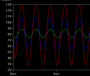
However, just as we use capacitors to isolate the input and output, why can’t we use a capacitor to short the signal to ground even if the DC path is through the resistor? As it turns out, you can. Try adding a capacitor across RE and watch the output go higher. Below, you can see the same output with a 47 uF capacitor across RE. Look at the scales. That 0.2V input signal now produces an output of over 5V, peak-to-peak. That’s a gain of about 25, or 5 times the DC gain.
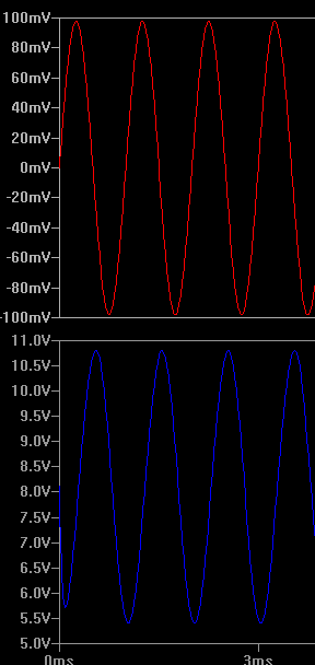
The effect varies on the value of the capacitor and, of course, the frequency. Here’s the output with 10uF, 47uF, and 100 uF capacitors (first graph, below). The second graph shows the effect versus frequency. You typically want the reactance of the capacitor to be about 1/10th of the emitter resistance at the frequency where you will accept a 3dB drop off.
Note that the capacitor works so well, that at some frequencies, we go beyond the allowable gain and clip (see the last graph). Depending on your design goals, you may need to be careful with that.
Selecting Coupling Capacitors
To know what value to assign the coupling capacitors, you need to know the impedance of the amplifier. That’s fairly easy to estimate, but with LT Spice we can do better. If you look at V2, you know it is putting out 50 mV and you can measure the current drawn from it. Ohms law will tell you that .05 divided by that current must be the resistance V2 “sees.” With C1 set ridiculously high (1F) and V2’s internal resistance set to zero, the circuit draws about 1.75 mA from V2. That’s about 28.6 ohms. So if you know the 3dB frequency you want you simply have to compute the capacitance using the familiar 1/(2*π*f*R) formula. Assume we want 10 kHz as the 3dB point. Since R is 28.6 you need at least 0.6 uF of capacitance. Of course, you can also reverse the formula and determine what your 3 dB point should be given a certain value of capacitor.
Here’s a little WolframAlpha tip. If you try to do the above calculation, you get the answer in scientific notation: 5.56 x 10⁻⁷. Sure, you can just shift the decimal point two to the right to get the exponent to -9… or is that to the left? However, you can also just add the words “engineering form” to your query, and you’ll get the answer to the nearest exponent that’s a multiple of 3.
Output Loading
The other problem you’ll often see is that you need to drive a low impedance load which can limit your gain since matching that impedance will prevent you from using a large RC. One answer is to use an output transistor as an emitter follower or common collector amplifier. This is a very simple setup where the input to the base appears practically unchanged on the emitter. So the gain of the stage is nearly 1. That might not seem like a great thing until you realize that the output impedance of such an amplifier is roughly the source impedance divided by beta. Remember, lower output impedance is good because you can drive a wider range of load.
Suppose your RC in the main amplifier is 1600 ohms and you would like to drive a 16-ohm speaker. If the emitter follower beta is 100, the effective impedance seen from the main amp will be 1.6K ohms and the output impedance of the stage will be very low. But because in this case, the emitter resistor is probably the load itself, you won’t want to put a capacitor in the output because it would block the path to ground.
Have a look at this design:
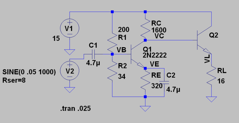
This is very nearly the same amplifier as before, but there’s no coupling capacitor on the output. In addition, the component values changed a bit. When Q1 is turned off, the maximum voltage will go to the load and this will transfer the most power when RL=RC so the output impedance at Q1 is 1600 ohms. This is a poor match for a 16 ohm speaker, but Q2 can get us in the neighborhood in the emitter follower configuration. It is true that beta isn’t reliable, so the match probably won’t be perfect, but it should be good enough for most purposes.
Here’s the output:
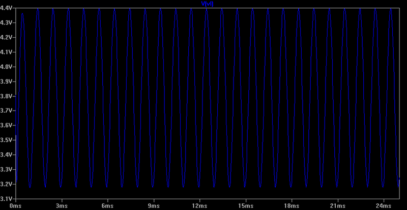
Compare that with the output of the original amplifier driving a 16-ohm load. You’ll need to reduce the input drive down to 50mV, but even then the output from the original circuit will be very disappointing.
Of course, Q2 is going to need to be a power transistor. You won’t be able to quite get all 15V on the base of Q2, but you could get close. After the emitter drop, you could have a Ve of about 14V and that’s a little less than 900 mA or around 13 plus watts. Picture a big device with a heat sink. Luckily, the simulation doesn’t care. But, of course, that’s also one of the dangers of simulation is that you can overstress the models and they don’t care.
The End?
As much as we’ve talked about the common collector amplifier, there’s a lot more to it. What if the collector load is a tuned circuit? Or the emitter bypass? You can construct lots of things including multistage amplifiers using this as a building block.
By the way, you might think that bipolar transistors are old-fashioned compared to FETs, but they do have their uses. Also, all of these amplifier configurations have corresponding FET designs. The ideas are the same but, of course, the design equations are a bit different. FETs operate on voltages and there are other peculiarities. For example, some types of FETs are normally on, so you’ll need a negative bias voltage to get them to turn off. FETs — especially MOSFETs — have very high input impedance which makes input circuits easy to design. However, they also introduce capacitance which can be tricky at higher frequencies. But that’s a topic for a future Circuit VR.


Thank you for these articles! I always learn something new from them!
Hmmm … that second transistor with 16 Ohm load will have something like 0.4-0.8 Amps flowing through it … It will get very hot very quickly, and die. Otherwise, very nice article.
Rats. I meant to take the 2N2222 off of there and put a higher power transistor on it and just didn’t. Copy/paste victim. That’s the danger of the simulation though is that the smoke doesn’t come out. Of course, a metal 2N2222 with a heat sink can do quite a bit but not that much.
Anyway, yes, that’s not a good choice of a transistor for that service. The real value is a little less, but still high. Q1 would have to be totally off (non linear) to get the 15V to Q2 and then the Vbe drop on Q2 will punch it down again. But you could get a good bit going through Q2’s IC anyway.
I will at least patch that on the GitHub if not in the figures.
Thanks, it will work great with second transistor being bigger and with a heatsink.
I admit that to this day I sometimes build class A BJT audio output stages, typically with speaker transformer. One has replaced burnt-out IC audio amp in a radio, and it still works after 2 years. That is the reason I immediately homed in on the dissipation problem in your figure :)
Thank you for your wonderful articles, for being able to take some criticism, and positive attitude towards readers.
>”This is why you try to match, say, a transmitter with an antenna or speakers with an amplifier.”
That depends. With antennas, you try to match the transmitter to the antenna to prevent the signal reflecting back from an impedance mismatch, but with amplifiers and speakers you do not necessarily want to match the impedances for two reasons: efficiency, and not frying your amplifier.
When the output impedance of an amplifier matches the load impedance, half the power is consumed inside the amplifier. That may be apparent or real power, but assuming both impedances are roughly identical, the amplifier is going to heat up, and you waste half your power on that.
Unless you specifically need to maximize the power output, you want the amplifier output impedance to be considerably lower than the load it is driving.
Thanks,
As I drive LEDs at high current, 100 of 5 mm in parallel, cooling things at 100 mph is important, in one project.
Where can I get 2N2222s in arrays of @100 long in case I drive the ws2801 too hard…20 to 30 mA peak, three channel in second project?
Thanks again
Just get some more modern and cheaper transistors, like 2N4401s or similar. Many other ones are ok, just check their maximum current ratings.
If more current is required, you need bigger transistors.
Continue reading →
Please