Ultrasonic phased arrays are one of the wonders of the moment, with videos of small items being levitated by them shared far and wide. We’ve all seen them and some of us have even wondered about building them, but what about the practical considerations? Just how would you drive a large array of ultrasonic transducers, and how would you maintain a consistent phase relationship between their outputs? It’s a problem [Niklas Fauth] has been grappling with over the three iterations so far of his ultrasonic phased array project, and you can follow his progress on the latest build.
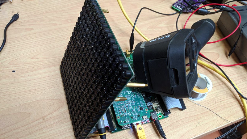
The arrays themselves are a 16 by 16 grid of cheap ultrasonic transducers on a PCB, fed by HV583 high-voltage shift registers. These chips have proven to be particularly problematic, their drivers having a relatively high internal resistance which leaves them prone to overheating.
An interesting solution to a problem comes from the transducers having a polarity, but because it doesn’t matter in their usual application, that polarity not being marked. He’s overcome this by using the STM32 he has managing power alongside his BeagleBone to listen through a sensor as the ‘Bone supplies each transducer in turn with a known phase. An internal map can then be created, such that the appropriate phase can be applied on a transducer-by-transducer basis.
It’s the fascination with the subject that we find appealing, this is version three and version two worked. Most of us would make one and call it a day. It’s something we’ve seen before from [Niklas], after all this is someone who plays with turbomolecular pumps for fun. Meanwhile if you would like to learn more about ultrasonic arrays and acoustic levitation, it was the subject of one of this year’s Hackaday Belgrade talks.


Geesh !
What an interesting project for all sorts of entertainment and stem demonstration school education opportunities. Didn’t know about the hv583 – intriguing for all sorts of E field electrophoresis experiments with nice v dynamic range, will be looking at this more closely for sure, especially how quickly I can change the whole array in one fell swoop not just the max data rate. Thanks for posting this article :-)
Is there any danger for humans or animal ears?
Highly unlikely at these power levels although I ‘hear’ some power distribution artifacts could be noticed at lower than transducer operational frequencies – depends how they are mounted and secondary effects of mounting methods ;-)
IOW: Ultrasonics at high enough power levels can cause considerable damage to living tissue you you wouldn’t hear a thing just find odd ball sporadic local heating – could be quite disconcerting – I have heard rumour it causes skin prickling effects as if pulses of high power TeraHertz emissions like the US crowd control measures suggested instead of tear-gas using modified radar with higher power output.
For worst case szenario assume the maximum of acoustic pressure fromm the tinylev (another selfmade-ultrasonic-phased-array) to be exposed of. Its maximum reaches 3000 Pa, which is equal to 160dB. Wikipedia says that’s ten times the noise of a 30m away jet plane. But you probably never Stück yours or you pets head in the middle of the levitator :)
If you look at the signal levels shown in the plots here, one emitter alone look to be just less than 40dB @40kHz I don’t think that it would be loud enough to cause anything more than an annoyance to an animal, and it is outside the hearing range of a human.
https://hackaday.com/2018/07/12/dual-sensor-echo-locator-gives-high-accuracy-at-low-cost/#comment-4738335
But a HC-SR04 is typically driven by a MAX232 Multichannel RS-232 Driver at +/-12 volts, where as the above is being driven by a HV583 128-Channel Serial to Parallel Converter chip at 80 volts. Very roughly 4x the applied voltage will generate roughly be 4x the deflection in a piezoelectric crystal.
But a 16×16 array, that is an interesting question what would be the signal level if all 256 were driven at exactly the same frequency (never going to happen, due to manufacturing tolerances in the piezoelectric crystals) and totally in phase ? Due to the manufacturing tolerances of so many non matched piezoelectric crystals there will probably be some constructive and destructive interference between emitters that generate beats within the normal audio frequency range of humans.
Yes, there is danger and I have encountered it from my ultrasonic project.
Ultrasonic sound is more like a beam than a wave, and will reflect off of just about anything. If the reflection hits your ear, you can get the sound at full volume and not notice it.
Just about any sort of ear protection will work, but you have to remember to use it. In my case, while adjusting a transducer the sound hit a recessed light fixture on the ceiling and bounced back and into my ear.
What effects did you experience as a result of that reflection?
How was the spacing determined?
could ultrasonic phased arrays be used for haptic feedback or for instance augmenting VR ?
yup! https://www.youtube.com/watch?v=kaoO5cY1aHk
can’t wait for us all to get these in 20M unit arrays the size a cellphone camera die.
.. for $0.30 a pop. seriously though, even on this scale it seems like quite the financial investment before one has a working setup like this.
Yep! we got a demo of the UltraHaptics product at our office a few weeks ago.
https://www.ultrahaptics.com/
The array looks identical to the picture above, and it kind of works – the effect is somewhat subtle.
Really cool! I wonder, when you purchased those $0.40 transducers, did you get any rejects like those shown here:
https://youtu.be/DqoAB3jJmOg
Really does need some simulation- and a bit more theory- I tried a similar project and found that the concept just does not scale well, particularly for the available sizes of ultrasonic transceivers. You can make something that has a great boresight peak, but the sidelobes destroy the directionality. After I built a small array, I did the simulation and found that the sidelobes did not get under control until the transducers were put at a spacing that was physically smaller than the transducers. I started to think about experimenting with sparse arrays and modulations- or even using a single large transmitter and small (but less efficient) receivers, but … SQUIRREL!
“16 by 16 grid of cheap ultrasonic transducers”. The lowest cost transducer I can find on Digikey is $3.26 at a qty of 256. Does anyone know a lower cost source ?
ebay, find a chinese vendor
Please send the link to the product on digikey
“eBay, find a Chinese vendor”
And ask for “Sample Price”..