Oscilloscopes are especially magical because they translate the abstract world of electronics into something you can visualize. These days, a scope is likely to use an LCD or another kind of flat electronic display, but the gold standard for many years was the ubiquitous CRT (cathode ray tube). Historically, though, CRTs were not very common in the early days of electronics and radio. What we think of as a CRT didn’t really show up until 1931, although if you could draw a high vacuum and provide 30 kV, there were tubes as early as 1919. But there was a lot of electronics work done well before that, so how did early scientists visualize electric current? You might think the answer is “they didn’t,” but that’s not true. We are spoiled today with high-resolution electronic displays, but our grandfathers were clever and used what they had to visualize electronics.
Keep in mind, you couldn’t even get an electronic amplifier until the early 1900s (something we’ve talked about before). The earliest way to get a visual idea of what was happening in a circuit was purely a manual process. You would make measurements and draw your readings on a piece of graph paper.
This sounds crazy, but the trick was to use a spinning rotor with a contact and a matching but movable contact. You’d move the contact to examine different points on the standing wave using a galvanometer (basically a compass with a coil of wire). The speed of the rotor would essentially be your sweep and you would hope the rotating contact was in sync with your waveform.
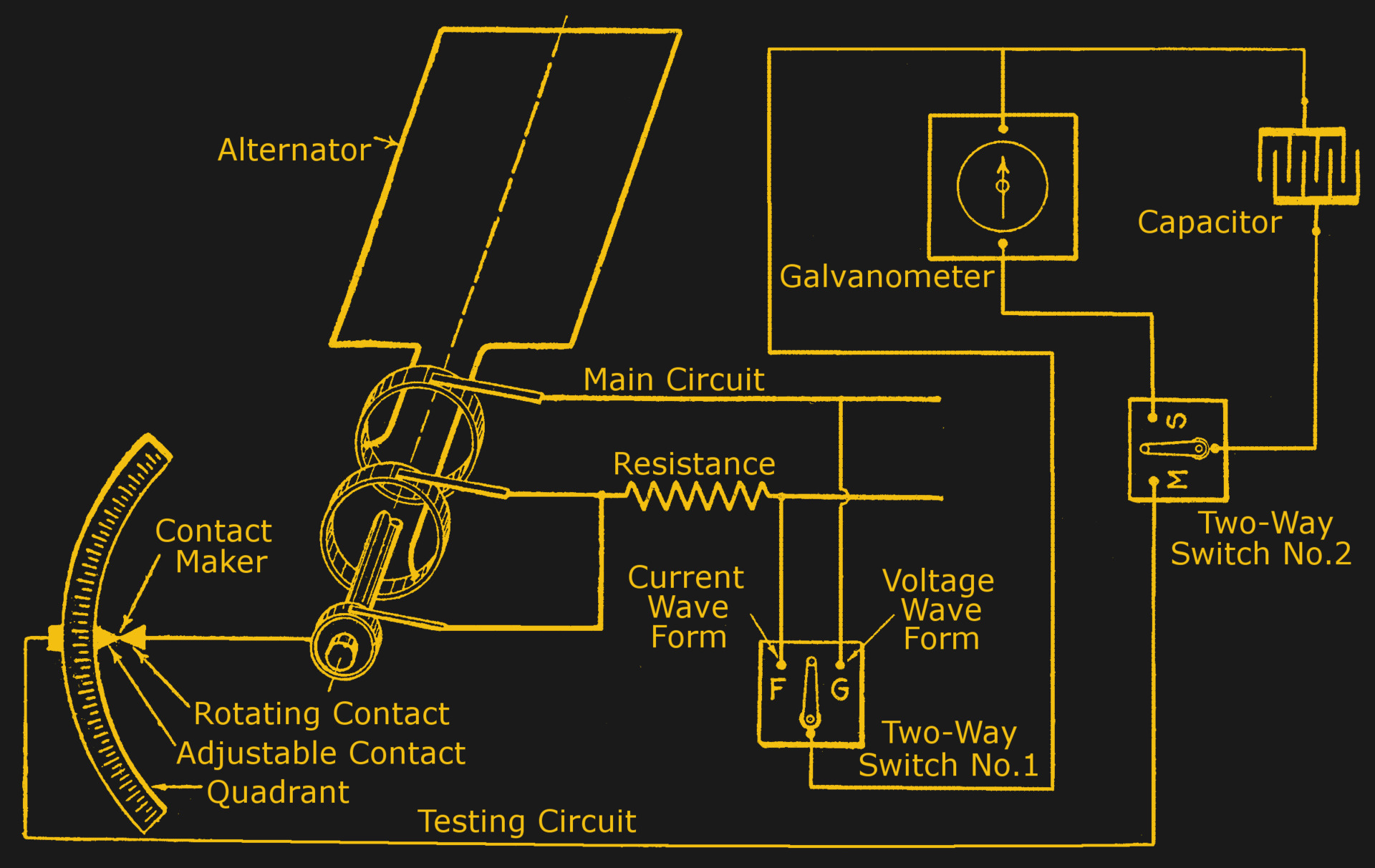
As you might expect, this was pretty crude and relied on the waveform being constant because your first and last measurement would be many cycles apart. The figure above shows Jules François Joubert’s system for semi-automating the processes which showed up in books around 1915 or so. In fact, there were several variations and you can read more about how it all worked in chapter 63 of Hawkins Electrical Guide.
Automation
Hawkins describes two ways to obtain a waveform: the step-by-step methods like Joubert’s, and the constant-recording method which includes cathode ray tubes, glow lights, moving iron, moving coil and hot wire methods. Remember, a cathode ray tube, at the time, was essentially a laboratory curiosity and required a lot of ancillary equipment and know-how to operate.
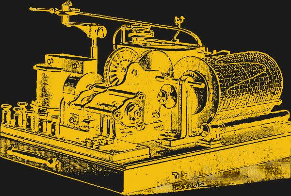 One automation attempt was to use the Hospitalier ondograph — a sort of automated Joubert apparatus. While not a catchy name, the ondograph used a synchronous motor geared so that the rotating contact makes one less revolution per minute than the motor does. On each pass, a condenser (what we call a capacitor) would charge to the measured value on the contact which then discharged into a galvanometer with a pen like the one to the left.
Another system involved connecting a mirror to the galvanometer and using a “falling plate” camera. A photographic plate (piece of film, essentially) would slide down under the force of gravity in front of a slit that allowed light from the galvanometer. Effectively, the falling film was the horizontal deflection and the mirror’s position was the vertical deflection. Clever, if mechanically complicated.
The Mother of Invention
There were many other ways to convert signals to visual using mirrors, lights, and even gas flames. One General Electric instrument used mirrors and a synchronous motor to project to a sheet of glass so an operator could trace the image to paper. One method that Hawkins describes as a “glow light oscillograph” appears to use a bulb like a neon bulb, but without the neon. Which electron has a glow around it would let you know if the current was positive or negative.

The synchronous motor ran at up to 125 Hz (cycles, in the Hawkins book) so capturing a USB bus transaction with one of these wasn’t going to happen.


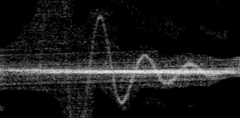
And what did the results look like? Not bad, we suppose, but it does make you appreciate your scope, whatever it is you have. Perhaps the best images came from using a movie camera instead of a falling plate camera. Don’t forget, though. In those days you’d have to develop the film, too.
CRTs
The CRT would eventually replace all of this before itself being largely replaced. Early CRTs — Braun tubes in 1897 — only had vertical deflection so a rotating mirror provided the horizontal time base. The idea to move the beam magnetically in the horizontal direction didn’t arrive until 1899.
In 1931, Zworykin produced a sealed CRT with a thermionic emitter that only required a few hundred volts to operate. Not long after that General Radio produced the first of what we would think of as an oscilloscope.
Well, sort of. The first scope — a 535 — was a collection of parts: a power supply, a tube mount, and the CRT. The type 635 scope in 1933 from General Radio (also called GenRad) had everything in one box but still lacked any amplifier or horizontal sweep circuits. The 687 was the last scope GenRad produced, in 1934, and it had the missing sweep circuit. It didn’t have any amplifiers, though. It was odd that the front panel of the scope was what we would think of as the left side and the CRT was by itself on the front. Or perhaps, the front was the panel and the CRT pointed out of the right. Depends on your point of view.
How Far We’ve Come
It is amazing how far we’ve come in less than 100 years. However, it is also funny to me that we might not invent some of these creative solutions because we’ve become so spoiled. You can only wonder if in one hundred years someone will be chuckling at our quaint way of doing computing, perhaps. Or thinking that we must have been geniuses for getting anything done in such a primitive environment.


“These days, a scope is likely to use an LCD or other kind of flat electronic display, but the gold standard for many years was.”
Was what? What? Come on, man, don’t leave us hanging like this!!!!
LOL! I’m beginning to think that typos and mistakes like this in the first couple sentences of HaD articles are some sort of signal or mind control…
I thought they were deliberate, to keep the nitpickers satisfied. If they didn’t have errors to gripe about, they’d have to find something else.
Michael
Back in 1986, I threw out an oscillograph that came in a box of auction items, because I had no idea what it was…
And Here I m in India, unable to afford one but fantasizing about it every day of my existence. It pretty much costs around 30-40K INR which is like nearly a months salary for most of the individuals.
Chinese digital o’scopes keep getting cheaper, with free shipping too!
Else, if you know someone who’s gonna visit western europe or the USA, ask if they can take one home. With a bit of luck you can find a free one, but usually for €25 you can find a simple single channel 15mhz model.
[Rohit shetty] I did not write “oscilloscope”, I wrote “oscillograph”, they are different, you could build your own oscillograph with a mirror and a meter movement, (finding light sensitive paper to display the waveform might be the expensive part). I did not know what an oscillograph was when I discarded it, because it was technology too old to be bothered with at tech school. I also threw out from the auction box some old variable inductors and capacitors, (mounted on wood blocks). Later I found out those were from antique radios. B^(
Funny that the connection terminals on the front of the GR 687 are thumbscrews, but the CRT terminals look like Fahnestock-style spring clips.
Typo???
“These days, a scope is likely to use an LCD or other kind of flat electronic display, but the gold standard for many years was.” finish that thought???
They got a little carried away in editing. I had original put something like CRT like a TV picture tube and I remember someone saying they changed that. But they must have forgot to paste it in. I just fixed it a different way.
They, the voices?
The voices in my head never stop. I just wish I knew Russian so I could understand what they are saying.
it’s not russian and they asking if you want the big gun or the good package.
Are you working with the U.S. Embassy in Cuba?
B^)
I mean obviously they mean CRT. What else do you think it was? A crystal ball? Typos happen, there’s always errata, use context clues and move on with your life.
I love my Almirante model 1973 “Crystal Ball” oscilloscope. The thiotimoline preamplifier is incredible and the way it anticipates what I want to measure is uncanny. It even starts displaying the signal before I hook up the probes to the circuit!
“The End ochronic Properties of Resublimated Thiotimalin”
” Thiotimalin to the Stars ”
Sorry about the extra space in your first title, autocorrect keeps adding it.
So Asimov caught on to non locality and retro causality before anyone else.
Nice.
How come they didn’t think about vibrating some mirrors and bouncing light off them?
That is what an oscillograph does, the light was then reflected onto photosensitive paper.
The mirror was connected to a taut wire galvanometer and the paper scrolled past the light beam to form the time dimension.
i have seen one that used a phospurious drum
“Which electron has a glow around it…” Electrode?
also: moving-paper chart-recorders, e.g. as commonly seen on seismographs.
I ran a Honeywell Oscillograph at Bussman’s test station for a few months.
Blew a lot of fuses.
The system involved a wet system. We had the photosensitive paper rolls, and I’d apply and adjust that in a darkroom. There was a portion of the oscillograph with gearing and a dark chamber and a sit that was similar to a dark slide on a camera which uses film magazines.
The article mentions the galvos, and I’ve got several of them which I bought later. They are I think around 1 microamp or so for pretty much full deflection, very sensitive. There is a light source with an adjustable slit and intensity which I never adjusted involved. You could dial up the intensity for fast signals.
We of course were blowing fuses with 60hz, but we could set for 110 to 10,000v and get a current and voltage signal to our instrument.
Biggest blow I ever did was a 250,000 amp potential 600v of a 5000 amp Limitron which is a silver element very fast opening fuse.
Copper element fuses would open in about 1/8 a cycle of 60 hz power (depending). Limitrons were so fast you’d have to look at microseconds to see the blip when the power came off 0.
Our blowing system would apply power to the circuit to do the blow at a positive 0 crossing by the way.
The wet development was a darkroom process till you had the “stop’ applied. There was only a development dip and then a stop dip of the thing with weights applied to the strip then let dry.
The paper was about 8′ across, FWIW, maybe 24′ long.
fun stuff. Wish I’d saved one or if I did have not seen it.
This was in the 72 or 73 time frame in Cahokia, Ill.
“The paper was about 8′ across”
8 feet across???
I have seen another type, long ago. It used a special type of glow discharge lamp which did rotate like a pov clock.
Interesting. A little while back I came up with an optical memory delay line using similar principles: yes it could display as well. The big problem would be matching the output screen so ambient light doesn’t mess it up.
Turns out you don’t need UV LEDs after all and regular cheap zinc sulfide screen from an EXIT sign works well.
I used a 7603 Tektronix scope and scope camera that used Polaroid film packs in the 90’s to capture one shot events of hydraulic pressure transients in an oil fired 400 MW power plant low NOX burner. We lacked a storage scope so the film did the work. We were trying to understand why the burner control valve seals were blowing out and we used piezoelectric pressure transducers to measure the pressure transients. Our work was a success found the valve seals were of the incorrect materia and a valve redesign was required. I am long retired and that old 7603 is on my workbench use today.
Surprisingly nobody thought to hack and modify a seismograph?
The moving paper, that’s your horizontal axis , the pen the vertical
Sample rate is how fast the paper goes through the machine….
Those were around as early as the 1870s
Didn’t have complex waveforms back then so it would work fine for AC and audio frequencies and current sensing
Not like they needed gigahertz of bandwidth let alone 100 mhz
Well they would have wanted that pipe dream