We like the ICE40 FPGA from Lattice for two reasons: there are cheap development boards like the Icestick available for it and there are open source tools. We’ve based several tutorials on the Icestorm toolchain and it works quite well. However, the open source tools don’t always expose everything that you see from commercial tools. You sometimes have to dig a little to find the right tool or option.
Sometimes that’s a good thing. I don’t need to learn yet another fancy IDE and we have plenty of good simulation tools, so why reinvent the wheel? However, if you are only using the basic workflow of Yosys, Arachne-pnr, icepack, and iceprog, you could be missing out on some of the most interesting features. Let’s take a deeper look.
Yosys Options
Yosys is software that converts your Verilog into a BLIF file which stands for Berkeley Logic Interchange Format. It has an interactive command line, but most people use it with a command string as part of a script. For example:
yosys -p "synth_ice40 -blif demo.blif" demo.v
The synth_ice40 is sort of a script, though, and it does quite a few operations for you. There are other commands you can use, too:
- check – The check command looks for errors in whatever you have loaded so far.
- show – Generates a “schematic” using graphviz (see below).
- write_verilog – You can write out an intermediate Verilog which might be useful to simulate to run down synthesis issues if you have a simulation library for the FPGA primatives.
- write_spice – You can also write out a Spice net list if you prefer.
Note that at the time I’m writing this, there’s a bug in the documentation page where — starting with attrmvcp — the descriptions are one off. That is, the description for chparm is supposed to be the description for check, for example. Perhaps it has been fixed by now. You might also notice a reference to commands to read VHDL automatically through a translator. Don’t get excited, because this has been removed in recent versions since all of the translators have some issues with certain VHDL. Of course, if it works for you, it is possible to do that conversion before calling yosys, if you like. There’s also a plugin for using vhdl2vl if you are brave. Or just stick with Verilog.
An Example
Just to look at a few of these features, here’s a really simple piece of Verilog that won’t win any prizes:
module test(input clk, input reset, input a, input b, input enable, output reg q);
wire q_intermediate;
assign q_intermediate=a^b;

// enable next line to see an error

// always @(posedge clk) q<=1'b1;
always @(posedge clk)
if (reset)
q<=1'b0;
else
if (enable) q<=q_intermediate;

endmodule
This module XORs the a and b inputs and latches the value on q at the rising clock edge if the input enable is high. Simple.
Instead of giving yosys a command line, just run yosys with no options. You’ll get a prompt. If you try entering the check command, you’ll get a message that you need to run proc first. So try that and then run check. You should see zero problems.
Maybe you’d like to see a problem. Uncomment the line between the assign and the always statement that says:
always @(posedge clk) q<=1'b1;
Now if you load the code, run proc, and then run check, you’ll see that the program knows you have too many things driving q. Be sure to take the line back out.
Once you have good code in again, you can try doing a synth_ice40 followed by a write_verilog command. Here’s the entire list of commands:
read_verilog test.v
proc
check
synth_ice40
write_verilog int.v
Now you have a file that represents the synthesized code. It is fairly long, partly because there are comments to keep track of the source file, but you’ll see FPGA primitives like this:
(* src = "/usr/bin/../share/yosys/ice40/cells_map.v:43" *)
SB_LUT4 #(
.LUT_INIT(4'b0110)
) _2_ (
.I0(a),
.I1(b),
.I2(1'b0),
.I3(1'b0),
.O(q_intermediate)
);
(* src = "test.v:6|/usr/bin/../share/yosys/ice40/cells_map.v:8" *)
SB_DFFESR _3_ (
.C(clk),
.D(q_intermediate),
.E(_0_),
.Q(q),
.R(reset)
);
A LUT is a Look Up Table. Because there are only two inputs used, the initialization for the table is only four bits and you can see that it is the truth table for our XOR gate that drives q_intermediate. THe SB_DFFESR module is a D flipflop, “obviously”.
Somewhat more useful is the show command. There are quite a few options, but for a simple circuit like this, just enter show. Assuming you have the graphics software on your machine you should see something like this:
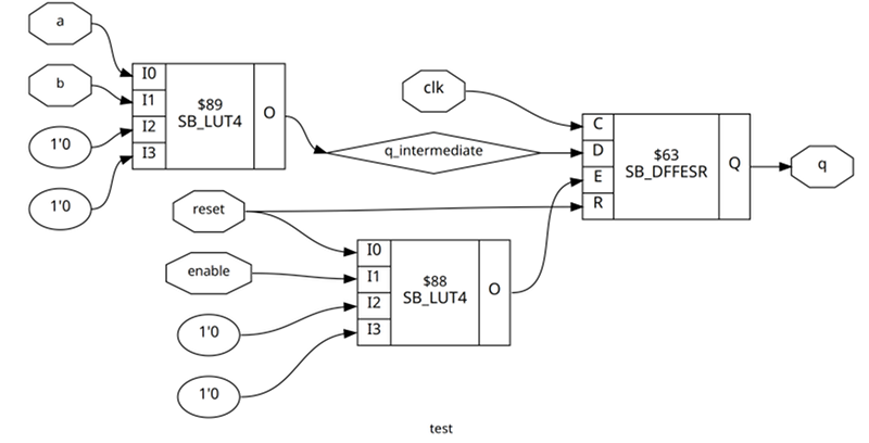
This is fairly easy to puzzle out, especially if you look at the output Verilog code, too. The topmost LUT is the XOR gate, while the bottom one is an OR gate that feeds the flip flop enable (E). This allows the reset signal to also enable the flip flop.
One other thing you might find interesting. Remember I mentioned that synth_ice40 is a script? Try typing this:
help synth_ice40
You can see what commands execute. You can also use labels to skip some of the processes if you like. There are also many other options you can set.
Timing Analysis
One of the problems with doing any sort of FPGA design is making timing closure. In the above example, for instance, you have to assume the a and b inputs are synchronized appropriately with the clock. If they were not, we’d need some more flip flops. However, imagine you had three of these circuits. Let’s assume one circuit processes A0 and B0 to generate Q0 and a second one generates Q1 from A1 and B1. Then the third gate has Q0 connected to A and Q1 connected to B to generate the final Q. Something like this:
module test_blk(input clk, input reset, input a, input b, input enable, output reg q);
wire q_intermediate;
assign q_intermediate=a^b;

always @(posedge clk)
if (reset)
q<=1'b0;
else
if (enable) q<=q_intermediate;

endmodule

module test(input clk, input reset, input A0, input B0, input A1, input B1, input enable, output q);

wire Q0;
wire Q1;

test_blk block0(clk,reset,A0,B0,enable,Q0);
test_blk block1(clk,reset,A1,B1,enable,Q1);
test_blk block2(clk,reset,Q0,Q1,enable,q);
endmodule
Even though FPGAs are fast, they aren’t infinitely fast. So the amount of time for the change in, say, Q0 to make its way into A could take more time than the clock if the clock were very fast. This would lead to bad operation. So how fast can the clock be?
With this simple design, pretty fast. You can use icetime to find out just how fast. Assuming you are using an hx1k device and you’ve already run yosys and arachne-pnr:
icetime -d hx1k test.asc
You’ll see this output:
// Reading input .asc file..
// Reading 1k chipdb file..
// Creating timing netlist..
// Timing estimate: 2.81 ns (355.34 MHz)
Since I didn’t constrain the design, your number could be slightly different.
If you add the -t option, the tool will show you the chain that is causing the highest delay which is what you’d need to work on if you wanted to increase the clock speed.
PLL Configuration
Speaking of clock speed, the Ice40 FPGA has a nice PLL onboard that can convert the clock input into nearly any frequency you want within certain limits. There are quite a few confusing configuration options, but you can use icepll to help you out. Suppose you want a 100 MHz clock from a 12 MHz input clock. Run this command:
icepll -m -f pll.v -i 12 -o 100
You’ll get a nice report and the pll.v file will look like this:
/**
* PLL configuration
*
* This Verilog module was generated automatically
* using the icepll tool from the IceStorm project.
* Use at your own risk.
*
* Given input frequency:        12.000 MHz
* Requested output frequency:  100.000 MHz
* Achieved output frequency:   100.500 MHz
*/

module pll(
input  clock_in,
output clock_out,
output locked
);

SB_PLL40_CORE #(
.FEEDBACK_PATH("SIMPLE"),
.DIVR(4'b0000),         // DIVR =  0
.DIVF(7'b1000010),      // DIVF = 66
.DIVQ(3'b011),          // DIVQ =  3
.FILTER_RANGE(3'b001)   // FILTER_RANGE = 1
) uut (
.LOCK(locked),
.RESETB(1'b1),
.BYPASS(1'b0),
.REFERENCECLK(clock_in),
.PLLOUTCORE(clock_out)
);

endmodule
Just include it in your project and create the PLL module in your top-level module. For example:
module top(input clk, output led);
wire fastclock, locked;
pll mypll(clk,fastclock,locked);
...
endmodule
Floorplanning
The output from show can be useful, but it doesn’t show you what’s happening at the chip level. One thing you couldn’t do, though, was easily view a floorplan for a design. But now thanks to [knielsen] you can do it in your browser.
A floorplan is like a map showing where on the chip your design resides and the wires that make the connections. This can often show you where you have bottlenecks, for example. You can’t actually make changes with this tool, however. In most tools, you can set constraints to move specific logic blocks around, but we don’t think arachne-pnr supports that today other than with I/O blocks, of course.
An Improved Script
In the past, I’ve used a simple shell script to drive the process. Given all these new tools, I’ve made it a little more complex. You can download the script on GitHub, but here are the highlights:
- A library path to find modules
-noautowireadded to theyosyscommand line. This has the effect of specifyingdefault_nettype noneon top of all files which is great for catching misspellings in signal names- Environment variables for
yosysandarachne-pnroptions if you need to pass extras in icetimenow generates a timing report (assumes hx1k)- Better error checking
You may want to tweak the script to your liking. You can change options in the file, in a .env file in the current directory, in the environment, and from the command line. This lets you configure the options for a folder then just issue the command (nominally ice40flow, but sometimes I alias it to go) and get a complete workflow.
Wrap Up
This is just some of what you can do with these great open source tools. Even tools like icepack and iceprog have interesting options. For example, icepack can set the bit that prevents the FPGA from putting the SPI EEPROM to sleep after configuration so you could use the unused portions in your design. Or if you ever wanted to try the FPGA’s multiple configuration option, ask for help on the icemulti tool.
If a tool works well, it is tempting to not think about it too much. However, these tools change and it is worth looking at what’s available from time to time. There’s even a new place and route tool in the works. It also doesn’t hurt to read the Ice40 datasheet, to learn what capabilities you can possibly use on this hardware.


One notable thing is how big that chip is compared to most CPUs.
The chip itself isn’t that big, it’s just in a large package – convenient for hand-soldering.
They come in different sizes. The bigger packages usually have lots and lots of I/O.
It has lots of pins – without the soldering complexity of a BGA.
Nice article!
Worth mentioning also is icestudio — which gives a ‘arduino-app-like’ experience with these chips — except it also does a fully data-flow GUI for hooking up simple logic!
It’s more of a ‘user’ of these tools though — it wraps them, much in the same way the arduino app does.
I didn’t know about nextpnr… interesting that it seems to support some of the Lattice ECP5 as well… Also interesting is that it’s associated with another project trying to do the same to support the series 7 Xilinx chips.
All I know is that $89 seems like a lot to pay for a look-up table.
The ICEstick shown up top goes for $50. There’s also the TinyFPGA BX, with about 8x as many LUTs (but maybe not as much I/O broken out) for $39.