If you want to plug a USB cable into your next project, you’ve got a problem. USB is not UART, and UART is what every microcontroller serial port wants. To add USB to your microcontroller project, you’ll need to add a support chip, probably from FTDI, although there are a multitude of almost-FTDI clones available from the other parts of the Internet. These parts are slightly expensive, and they require some support circuitry. What you really need is a simple device that requires minimal external components, takes in serial from your microcontroller and spits out USB, and costs no more than a dollar. Bonus points if it’s hand-solderable.
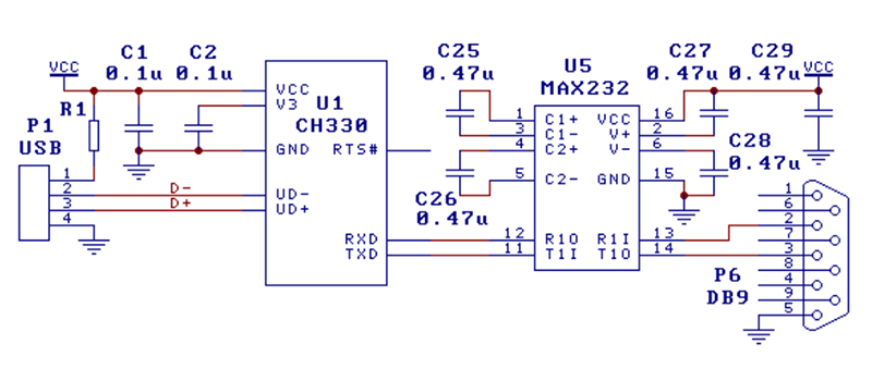
 The CH330 is apparently the answer to this problem (That’s a TaoBao link, this is probably going to be the best link going forward). It’s a dead simple chip with eight pins. Two are the data lines on a USB cable, and two are TX and RX for your microcontroller. The other pins are just power, ground, and an RTS line. Best of all, it only costs about fifty cents. You’ve never heard about it, because a few hours after this post is published, it will be the most information you’re going to get on this chip in the English-speaking world.
As far as we can tell, the CH330 is the smallest in a line of USB to UART converters from WCH, although the part isn’t even on the company’s website. The first reference to the phrase ‘CH330’ in reference to a USB chip appeared about a month ago, at the beginning of September. There’s a GitHub for someone who is apparently using this chip in a Pine64 board, but that’s about it. There’s no more information.
Right now, the only documentation for this chip is a single Chinese-language datasheet with an example schematic showing this chip connected to a MAX232 as a USB to RS232 converter. This is it. You’re looking at all the information that exists on this chip in the English-speaking version of the Internet.
The idea of a cheap, small chip that easily turns USB into UART would be great for thousands of projects. An FTDI chip will work, yes, but if you’re making thousands of a thing you might want to go with the fifty cent part over the two dollar part. That said, we’re in untested waters with this part, and you can’t even find it on AliExpress.
Let us know if you’ve gotten your hands on one of these devices. This has the potential to be really useful in a lot of projects and products, and we’re eager to see what the community comes up with. Thanks to [acabx] for sending this one in on the tip line.


Even better https://lmddgtfy.net/?q=CH330
Hey, clown! Maybe you should actually look at the search results actually are before telling people to run a search. Yeah, so DIAF. ;)
Actually both DDG and G prefer sugarcane harvesters to USB chips.
I’d buy a Sugarcane harvester for $0.5..
I’d be happy just getting the Cutler-Hammer 3 Pole 30A Breaker for 50 cents.
LOL he failed
https://www.deere.com/en_ASIA/products/equipment/sugarcane_harvester/CH330/CH330.page
I had no idea that sugarcane was grown in India.
An especially memorable treat from my visit to India was freshly squeezed cane juice. Milk-like and delicious.
Like in Brazil.
Cachaça.
If that wasn’t ironic (then… well, yeah: whooosh) — kids, check your history.
Sugarcane is original to South & Southeast Asia. It was brought to America as part of a complex colonial and embargo situation by the then European superpowers (and which must have cost lots and lots of African people their lives, dignity and everything).
Does Deere enforce their DRM in India?
I’m sure they try, but I’m also certain the locals will give zero fucks.
Well, the Americans wouldn’t give any fucks either, but their only alternative these days is to buy tractors from someone else. The tractors will just refuse to run if not maintained by JD.
https://hackaday.com/2017/03/24/the-icon-of-american-farming-that-you-now-have-to-hack-to-own/
I got a 30A 3 pole breaker from cutler hammer. I think my hand will get tired switching that fast enough to make a passable USB signal.
wow, adding a tractor and a 3 poll circuit breaker can replace a FTDI chip? give this man the hackaday prize /s
Whoah hold on there, man.
You also need a ball point pen.
Wonder if it works with generic drivers in Linux. That would be great! That, and stable 115200 at 3.3V.
I’m pretty sure it does work with the generic Linux drivers. Way back, I think even before the FTDI debacle, I needed to put a USB programming connection on an Atmel AVR. When I saw the $8 price on the FTDI chip, I recoiled – that was about four times the price of the microcontroller! Anyway, I searched the usual Asian places and found CH330-based boards for about a buck. This seemed like a too-good-to-be-true situation, but I did find the Chinese datasheets, which were sufficient – the reference schematic gave all the information I needed, and I bought four of them. They worked fine, using Linux, but I don’t think I’ve ever tried them in Mac OSX or Windows. No idea how stable they are at 115 kb, and I’ve only used them at 5V.
Hm. Looks like those were actually CH340s. Never mind.
Certainly not with the generic driver, but it will probably be part of the CH341 driver someday:
https://github.com/torvalds/linux/blob/master/drivers/usb/serial/ch341.c
It does work with the CH340 and CH341 driver. Tested it with my board https://github.com/Jan–Henrik/CH330_Hardware :3
It will, but not great. The mainline driver has a bug where it doesn’t enable hardware handshaking properly. The WCH supplied driver fixes that, but even then I was having a difficult time with lost bytes and buffering issues.
Ended up ditching the chip and implementing USB-Serial directly on the ARM chip I was using…
Errrrm is this not the smaller brother of the CH340?
Yes hackaday is being dramatic. It is clear from the context that this is the same as the ubiquitous CH340 trimmed down (possibly literally…) to have the absolute minimum needed for making a usb/serial bridge. Unclear why it costs twice as much as the CH340G (available $.25-$0.3 in small quantity, less in larger quantity), hopefully they will come down in price with time.
Somewhat annoyingly, you get RTS but not DTR which means it cannot be used for normal arduino programming. Would have been a nice way to save space on the smaller arduino clones.
Ch340 requires 12Mhz chrystal, while this one seems to work without.
Be aware that the implementation of a clock on chiplevel with such precision comes with additional effort. If this is really the reason for the price I cannot judge…
There is the CH304C that does not require a crystal at all.
The CH340C is great, although last time I looked it also only had Chinese documentation and couldn’t be bought from most of the usual suppliers either. Still, it doesn’t take too long to figure out how to use.
Likely it trims its rc oscillator periodically to the recovered USB clock from upstream. Many other micros have this capability.
AFAIK they originally used RTS some time before the Uno but switched over to DTR as many terminal programs would send a RTS pulse when they were opened (and thus resetting the arduino)
Avrdude toggles both DTR and RTS, either is fine to use if your USB-UART chip supports controlling it (I have a vague feeling that there is a chip that doesn’t support RTS control, but can’t remember which)…
http://svn.savannah.gnu.org/viewvc/avrdude/trunk/avrdude/arduino.c?revision=1321&view=markup#l92
So does this mean you would need to reset manually to reprogram instead of auto-reset?
Just ordered 100 from this site: https://lcsc.com/search?q=CH330N
And the manufacturer hosts the datasheet (in Chinese, sure): http://www.wch.cn/downloads/CH330DS1_PDF.html
Do you need all 100? If I send you a SASE and a couple bucks, would you share 2 or 3? :D
Why not just buy 1 or 2 from the site I linked to?
Don’t be such a whiner, Kris,
oh, wait, you can’t help it.
B^)
Yes, the “h” is silent…
Neat, they also offer combined shipping if you order PCBs from JLC-PCB /”EasyEDA”. Thanks, good find!
And don’t forget to collect on the $4 off coupon on your first order. I missed this and lost $4 :<
If you order one or two and use the cheap shipping they will have to pay you!
Entertaining site to browse – 8 pin uCs for $0.04, with English datasheet. Crazy!
Hmm, interesting I see OTP 8 pin CPUs for as little as USD O.0294 each in 100 off, just need a low level x-ray exposure such as a s/h dental unit to erase them Or a b/w monitor with the eht turned up a tad :D
Certainly worth browsing as potential for all sorts of products you would hardly expect to have processor doing something useful about as cheap as a 555 – Lol ;-)
Hmm, that’s an interesting way of erasing OTP memory, could you elaborate?
Ah well Mark, it’s reasonably straightforward issue with few things to watch. Essentially the energy to erase a cell in eprom parts is UV light of appropriate spectra and it need not be a specially narrow line so if your UV source’s peak is a bit off it doesn’t matter that much you just leave it on for longer with attention to thermal issues as long as there is some width to the bell curve. In the case of OTP devices there is no visible window, well unless you make one by grinding very carefully or judicious use of DMSO with a big But, avoid skin contact unless you really want some (maybe useful) chemicals to pass through your skin to various structures !
Low level narrow beam x-rays (such as dental) or carefully focused old b/w monitors with higher EHT (no colour shadow masks) aren’t that far from upper UV spectra so they will pass through the epoxy and by various scatterings and re-emissions overall offer enough energy to erase those cells over range of times but, there are thermal, saturation time caveats and with so called relaxation times due to electrostatic effects of charges building up on the inside epoxy possibly causing ESD type issues – few simple ways around that. If you want to try this on any sort of scale of investment you must get a fluorescent film if at least to protect yourself as well as pinpoint best aspects of beam spread. There are other potentials to do the same if you have access to tight Cs137 or Co60 industrial sources – that has a whole other set of issues beyond scope on this forum…
I thought XRays didn’t work to erase EPROM cells, mainly due to the silicon being too transparent at those frequenies?
Also, I’m not sure modern OTP chips use UV-eraseable cells; hasn’t flash memory long-since gotten much cheaper to make, meaning that an OTP part may be flash without the extra circuitry needed for “erase”?
I see my post with more detail was awaiting moderation, should be able to see it now.
The tech from eproms to flash uses same basis
https://en.wikipedia.org/wiki/Floating-gate_MOSFET
It’s all about adding or removing charges on floating gates, the tunnelling issue interesting.
I’m not saying the x-ray method is completely reliable or even fast, there are ways to make it better though prob not worth the effort given the low cost of OTP parts eg as little as USD 3c ea in 100off etc.
It’s correct some perhaps most x-rays will pass through but, according to spectra breadth and there are secondary factors in respect of re-emissions in respect of flux direction, not as simple as single direction source. In any case flash not long term as the charge can degrade, bit more complex other re ferroelectric in conjunction can make it last a lot longer, details escape me
Even small ARM chips for 0.42 usd. It is a CortexM0 core with basic peripherals as timers, gpio and watchdog.
I got one and translated the library and added support to blackmagicprobe.
See for more info: http://smdprutser.nl/blog/the-arm-chip-that-wont-cost-an-arm-and-a-leg/
I think those penny cost uC’s will be next :)
I’d seen that and, like others, not been able to find them. Now I can :-)
I’d also found the GD32F103s on there, and only just realised that’s you too. Do you ever stop?!
Used on this board from yesterday:
https://hackaday.com/2018/10/02/tiny-wifi-enabled-arm-mcu-for-tiny-projects/
Was just gonna say that, I saw that SOIC-8 and immediately went on a 15 seconds search mission to AliExpress, but no luck. Would be really nice if (when?) we can get a sweet strip of 100pcs from the usual entrepreneurs on AE
lcsc claims +18000 in stock for $0.35 in singles
+1 thanks for pointing us what hackaday writers can’t
You can get the datasheet here: http://www.wch.cn/downloads/file/240.html
Google translate will actually do a good job of translating the entire document here: https://translate.google.com/?tr=f&hl=en
I have been just translating the PDFs using https://www.onlinedoctranslator.com which uses Google translate but seems to keep the formatting somewhat the same.
I wonder if FDTI ever reevaluated their pricing and their conduct.
Neither!
They’d need a searing fine before that happens
To be honest, they don’t need to.
I don’t think I am the only one to do this, but when I need a USB->UART bridge, I will normally use the CH340 for my home projects, but when it comes to work, I only use FTDI parts, simply because they are reliable, and the drivers are already installed on any operating system, which saves me a lot of time answering calls from engineers asking how to use the new board. Those are a couple of extra dollars well spent.
I occasionally use the CP2102 by Silicon Labs, which usually works first time as well, but not everyone has the driver for it, despite it being easily available.
I am still a bit puzzled that anyone would need a driver for a CDC USB device. I just bought a fake arduino coming with a CH340, the arduino IDE wouldn’t recognize the device without installing the driver, while Serial would see it just fine.
It has something to do with the name associated with the ch340 and theArduino environment.
My observation is that it has a “space” in the name and the Arduino environment doesn’t like it-
the CP2102 is way better than the CH340 – it goes faster and is more reliable…
Why bother when just about every PIC32 core has USB available…
PIC32mm is also gaining support in chipkit slowly and it goes for a $1.50 or less for a 25Mhz 32 bit chip + USB
PIC32 is usually an overkill for simple projects. However, I like 18F2550, it has native USB support and is decent microcontroller with specs that are pretty similar to ATMega328 (form factor, speed, RAM, ROM). I think there is even some 16F chip with native USB hardware, didn’t use it yet.
Indeed… and buy a device from a known manufacturer (well here in NA anyway) which means support and longevity (has Microchip ever discontinued a part?)… and one can buy it from the usual distributors.
Generalizing from PIC to any MCU with a native USB block, the answer is still simple – complexity! To even output a single-character ‘hello world’ character, you’ll need a somewhat decently featured USB stack which can easily cost ‘a few’ to several dozens kBs of code, and probably a kB or more of RAM. You’d need to configure DLLs, DMAs, IRQs i.e. many dozens of HW registers, do the enumeration dance and send descriptors, maintain an FSM for the link status etc.
Compared to configuring a typical UART block : writing 2-3, maybe a handful at most, HW registers and then simply busy-wait on an data-register-empty flag in some status reg, and loop out a byte at a time through the data register. Only a few dozens of bytes of code and maybe some negligible RAM required. Even with a fancy interrupt-driven circular buffers implementation, you’d only need some 100s bytes of code and RAM dictated by how much you want to spend on your buffers.
So, as a debug output and basic simple dbgcmd input terminal, an UART is hard to beat. So simple it can be brought online among the first steps of the reset handler (startup code), or in a bootloader, or to do a simple stack dump in a hardfault handler. A fw USB CDC driver is unfeasible in any of those use-cases.
@mj
I guess it would depend upon what MCU you are using. I typically use NXP/Freescale’s Kinetis MCUs and it is trival to get USB working… Download the free software tools, add Processor Expert’s USB stack, and you are done. USB driver is a standard CDC. All is all I can add USB to my Kinetis MCU in minutes…. and then bolt that to whatever application I am working on.
I find the killer with on-MCU USB stacks is that while you’re developing/debugging each time the MCU gets reset the USB stuff has to re-enumerate.
Which isn’t a problem if you delegate the USB task to a separate ATtiny microcontroller.
Yes, it can be easy as pie to include and configure a pre-supplied USB-stack, but that wasn’t the point. If you look into the generated/included stack’s source code, you’ll probably see that it’s still a lot of low-level HW setup and management going on “behind the scenes”, from the user’s (i.e. your, the developers’) perspective.
Which is fine, for the typical use-case – except maybe you’re still probably hit with significantly larger memory footprint for the stack & CDC driver, than a basic IRQ-driven UART driver.
Sill, as Thorsten said below too, the main problem with USB/CDC as a debug-channel, is that *for some usecases* USB is useless simply because the link is not available when it’s needed. E.g. for debug-prints during development of startup-code (think: reset handler), or development of your own custom bootloader, or doing your own custom basic stack-dump or similar in a hardfault handler. When the hardfault occurs in a buggy USB-stack, guess what has happened with the link when you try to transmit a CDC TX packet within the exception handler…
Granted, these are not the typical usecases for most users, most of the time. It’s just examples of situations where native CDC is simply not available, but a UART – possibly with an external bridge, like FTDI or CH3xx – would save the day.
Or, as Thorsten said, to maintain the debug link through a MCU reset (incl. eg watchdog bites)
SiLabs Cortex M0+ EFM32HG3 have crystal-free USB for $1.40 each in USA.
Interesting chip that CH330N. Just hope it isn’t rebadged ATTiny85 with software USB stack.
Shhhh!
You’ll give the whole thing away!
Don’t joke, I recently discovered that my Siberian Husky was actually just a German Shepherd in clown makeup
Why? How does it matter if it’s based on an ATtiny???
At least if it was a rebadged ATtiny85 you would have a datasheet with well defined hardware characteristics.
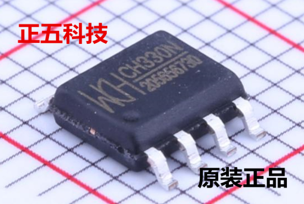
It’s not, by the way – the ATtiny85 uses the EIAJ “wide” 8-pin SOIC and the photo looks like your typical JEDEC 8-SOIC which is not as wide.
Maybe it’s an ASIC ? :)
I did some tests with the CH330N and I write down all my findings at: https://hackaday.io/project/162389-ch330n-33-usb-to-uart-info-and-applications
It’s not a re-branded Attiny85, it’s more like a CH340 with internal oscillator and fewer functions/pins. I’ll add much more info to that page!
Is this news? I mean it was on the front page of Hackaday yesterday, https://hackaday.com/2018/10/02/tiny-wifi-enabled-arm-mcu-for-tiny-projects/
Didn’t anyone else notice it in the photo?
Yep sure did. But the ensuing 15 second search for an AE source came up empty. Let’s spread the word so the supply chain wakes up :)
It is a rebadged 8051 8-bit MCU, check out the “datasheet.”
Somebody who speaks chinese could help the community and translate that datasheet… after all, it is just 9 pages
yeah, too bad we don’t have someone like Bunnie Huang or Naomi Wu to help us out.
Eight pins, and pictures too, how hard can it be?
Is it just me or does the one in the picture here look really nasty where the case is glued together?
It does look really nasty, but it isn’t glued – the package is epoxy molded over the lead frame, which is standard for SOIC packaging. The nasty edge is where they broke off the mold flash. Probably just a really low quality mold.
Is is just me or does the pic look really nasty where the two halves are glued together?
Hey now, don’t abuse lmgtfy! That’s supposed to be for when people ask stupid questions after not reading TFA. If you put it IN TFA then it loses it’s meaning!
I’d still take the CP2104 over this piece of junk any day.
Why you say? It has a datasheet. It has absolute maximum characteristics. This means I know the voltage, baud rate, USB speed limits if the chip. None of this it might work but in might not business.
I’ll stick with FTDI over any thing else. even the CP210x. Why? because when you plug in a FTDI part into a windows PC the drivers are already there, unlike CP210x and others. I dont need driver hassles.
I didn’t know Curtis Jackson was doing chip development now. Kind of makes sense to keep his options open in case the rap music doesn’t work out.
The CH340C has already been around for a while, internal RC oscillator and no crystal. Pin compatible with the CH340G, you just leave the crystal pads NC.
The CH340E is also available already, which is a very small 10-MSOP. Reducing the pin count and saving space since nobody ever cares about all the UART handshaking lines is a good move.
Good that they’ve noticed that so many users these days want at least one appropriate handshaking line bought out for “Arduino-style reset”.
However, it would be really good if they could bring out two handshaking lines such as both RTS and DTR so you can do “ESP8266 NodeMCU style” programming handshaking on both the reset line and GPIO0. This is an existing issue that prevents the use of the CH340E in these applications.
Could use serial break for reset. I think there is an implementation of it already.
So for a regular Arduino clone could you tie RTS to a capicitor to the reset line since we do not have the DTR? I think that would work.
I’ve been using these cute “CH340E” modules from Baite Electronics: https://www.aliexpress.com/store/product/1PCS-CH340E-USB-to-TTL-Serial-Converter-5V-3-3V-Universal-Not-need-switching-Model-BTE17/213957_32821571106.html
That’s a chip, a connector, and two LEDs – TH and breadboard friendly – not occupying much more space than a full-sized USB-B connector, for well under $1. From an AliExpress dealer that I’ve had good experiences with. (ok, I’ll admit to not have conducted extensive testing on bulk quantities. And it does bug me to be using a chip that I can’t buy from a “real” vendor.)
>>> I wonder if FTDI ever reevaluated their pricing
To be fair, FTDI announced a whole series of newer USB interface chips (the FT231x and similar) that are less than half the price of the infamous FT232RL, and has done a good job at getting their chips into “traditional vendor” channels (compared to the early Arduino days.)
It looks like you can get the slightly more common CH340 on aliexpress for 0.44 a piece. (5 pcs for 2.20) with free shipping. I know you can get drivers for that in Linux and Windows because it’s in a ton of common USB-UART cables. It has a datasheet also.
Oops, I started this comment, then saw yours was similar and was going to reply instead. But yeah I agree.
Ah interesting, slightly bigger chip though more capable. Claims to handle parallel port so given there is no 8bit bus, can it appear as a parallel port device in windoze and accept data then shift it to serial for output ?
I can already do this with an ATTiny85 in a smaller pin format. I don’t need 115K as long as I can do 9.6K we are good. Hook two together and now you have a serial bridge and an ISP programmer in the same square inch.
Ah I could do with something like that for when travelling though need a micro USB connector guess it just have been done few times interested in getting a couple,
Oops on tablet accidentally pressed ‘report comment’ can’t revert it from here, sorry :/
Yup, you can get pretty tiny, https://i.imgur.com/xnHMIT8.jpg This one happens to talk CEC and USB rather than UART and USB, but the concept is the same. The accessory chips are a 3.3V LDO and a pair of mosfets for CEC.
Cool a thread specifically on this issue, anyone have from 10 to a few dozen chips around in Australia ?
I don’t get it. FTDI has a FT230X that is a 16-pin SSOP and the same amount of required circuitry – just a single bypass cap. And is $2 qty/1 on Digikey. And before you reply, the bead, termination RCs, and shield filter listed in FTDIs datasheet is good practice – even for this IC (plus ESD diodes).
Also the CP210x is garbage. It requires the host to continually send USB packets to the device to poll modem status signals. It’s not like CDC where a separate IN-endpoint is used to push modem status changes asynchronously. Sure it ‘works’ but not ideally.
USB 2.0 always polls for data. In USB 3.0 they introduced ability for device to start transfer, but all standards before are polled from host.
Umm. It’s been a few years since I last read the USB spec, but I’m Pretty Sure all USB (<= 2.0) packets begin when the host (and only the host) starts transmitting the sync preamble. host == bus master, all downstream devices are only 'slaves'.
In essence, this means that all 'in' flow is polled, anyway. Endpoints are just the equivalent of 'sockets'. They can emulate being asynchronous, if they're configured 'like' an interrupt, but its actually up to how well the host root hub H/W + driver + OS stack can schedule everything as to how well it works.
It's fairly telling that max 'iso' flow rates are very very low (especially in the context of USB 2.0 Hi-Speed, which is 480 Mbps, as opposed to USB 2.0 'Full Speed' which is very common, but actually only 12 Mbps. ). They're ok for audio use, most of the time, but no good for anything faster.
So, all reads from IN-endpoints (whether configured as bulk, iso, or int) require the host to initiate every transmission — no device may drive the bus at all except within the packet (right after the host has just, during that packet, asked it to speak). So whether a different endpoint or the same, it's still all* polled.
USB 2.0 HiSpeed didn't require that the root hub use a stage machine with provision for host-side DMA transfer to handle the higher data flows without dropouts, unlike FireWire which did require DMA support (famous security hole though).
This was the key issue why FireWire 400 was so much faster/smoother than USB 2.0 Hi-Speed, since FireWire allowed for anyone on the bus to meaningfully communicate in real time to anyone (it's a peer to peer protocol) even allowing sensible QoS for higher priority traffic. Trouble is, it's too complicated. Go skim both specs, and you'll understand. FireWire is beautifully elegant, robust, well-designed, and vastly more complicated than USB's simple 'host is the dictator, no one else speaks unless spoken to' design.
*: Devices may trigger bus re-enumeration by messing with the bus in specific ways, but there's not a provision for any device to request normal service, a-la an IRQ. Not until you get to USB 3+ with its additional super-speed, PCIe / SATA like dedicated rx/tx lanes. Those work very differently to USB's packet design, they're much more like PCIe / SATA / GbitE etc — the clock is mixed in with the data, and the serdes units extract both the clock and correct phasing continuously, rather than relying on a short burst after a synchronisation preamble like USB/ 10/100 ethernet.
USB 2.0 is backwards compatible with 'FS' and 'LS' devices, so the packet preamble has to be slow enough for the slow devices to recognise when they're not being asked to 'talk'.
But all device *must* talk when told to, within a timing expressed iirc in microseconds.
All of which is a long way of saying: If you're getting poor performance with that chip, it's probably not so much that chip's fault for doing that, per se. Its probably got more to do with something in your specific root hub HW + driver + OS + App chain. Poor behaviour anywhere there usually adds unnecessary ~ms+ scale timeouts to the packet poll schedule, which easily messes things up when packet timing is usually at a 10's microsecond scale.
You may find a different story if you try testing with any one of the actors in that chain switched out.
It *is* annoying when vendors don't use the profiles though. Windows <10 always annoyed me with insistence on 'installing drivers' for things which were totally on-profile. Thank god they finally caught up to where every other OS has been for decades.
+1 remydyer
Good clarification with few things I didn’t know, thanks
I’ve always used the Cypress 65213. Costs less than the FTDI and is stable.
Has this new kid on the bus an EEPROM or the like to allow changing the serial number or some other detail for making multiple such chips distinguishable? I definitely need to chisel individual names with UDEV rules for not losing track which USB serial talks to which minion.
For CH340 I didn’t find a way and tool to do this. I was told they lack this feature. So I gave away all but one minion with such crippled chip inside. Result: The last one now is unique… :-P
Mwhuaaahahahahhhaahahaaaaa hrrrr hrhr hrrrrrrrrr…
Prolific PL2303SA ?
+1
I like that it has the added benefit of working with 1.8V devices also.
I also like the Microchip USB->UART bridge. It doesn’t have any noteworthy features and is not particularly fast but it is a standard USB-CDC device. This means no driver is required on a modern Windows, Linux, Mac or Android.
If installing a driver is fine I usually use the CP2102 for professional things and CH340 for home or less critical things. I used to use FTDI but don’t dare to anymore after this driver debacle.
It seems as if the RTS pin can also be configured as TE (transmit enable) for RS485 transceivers :-)
There’s plenty of cheap Arduinos using this chip already, has been for a few years. It can require you to download the driver, but once that’s done, it’s fine, works fine, you wouldn’t even know it was there.
Beats the shit out of FTDI’s shenanigans, and also cheaper.
Just updated my ESP32 development board design to test this CH330N chip; should know if a couple of weeks if it works as well (or not) as the FTDI FT230XQ.
https://www.oshpark.com/shared_projects/OVNKWWBB
Did you manage to get this working? I have the same setup and Windows 7/10 both does not recognize it. Only part I don’t have is a cap on the V3 line.
I also noticed that the RX/TX lines are at 5V levels.
I am waiting for my pcbs to come from OSH Park, probably this week. I did get the 100 ICs delivered.
It is not clear that RX/TX are 5 V. it is a bit confusing I admit. There is a 5 V VUSB input to VCC. I simply bypassed V3 with a 100 nF cap as shown in the schemaitic. I am unclear whether this needs to be connected to board 3V3 as an input. The data sheet isn’t very clear to say the least.
On the FT230QX the “V3” is a local 3V3 power source that is disconnected when USB power is disconnected. I assumed the same here, so I connected RX/TX indiocator leds using this V3 power source.
I’ll assemble one of these and see if I can get the circuit to work. Could also be driver issues, etc.
The uncertainlty is half the fun;>
Fixing RX/TX is not a bit deal. Level shifters or Adafruit trick(1N4148) on the RX pin. https://cdn-learn.adafruit.com/assets/assets/000/048/352/original/adafruit_products_schem.png?1511209629
For 3.3V setup, please feed both VCC and V3 with external 3.3V source.
On WCH USB2TTL chips, VCC is used both for input for an internal LDO and the voltage level, and V3 is both the 3.3V input and the internal 3.3V LDO output. (btw don’t feed VCC with anything lower than V3 or the chip will be killed, so only 5V and 3.3V are available).
My own 5V/3.3V switchable design always connect V3 to an external 3.3V fixed LDO, and VCC to the voltage select jumper.
Yep, pin 8 is the output of an onboard 3.3v regulator. I don’t know how much current you can draw from pin 8 before it falls over, but it powers an ATtiny1614 without any issues. You can also use it to drive a 5v to 3.3v level shifter on the Tx line.
Oh, and Linux? recognises it as a CH340 (most likely the same chip in a different package) and works fine. At least it does on my Ubuntu rig. YMMV
Pin 8? or did you mean pin 10?
Holtek HT42B534-1 is even better since it offers English datasheet, standard CDC class, internal level shifter and EEPROM for custom vid/pid/device name for the same price.
Thanks! Excellent information, and that datasheet looks significantly more complete than for the CH3xx variants.
For anyone wondering, the ‘LCSC’ site stocks these as well.
https://lcsc.com/search?q=HT42B534
Turns out Holtek even has distributors in our region. We were able to buy it in bulk for even lower price than on lcsc or taobao, shipping and taxes included. So far the only problem found is that the chip requires TX pin to be pulled up during power on reset.
Great find mj, hrmm – will be putting together an even bigger order over weekend for all sorts of things, sorry no sales commisions for you this time, qudos though as I hadn’t bothered to check that site for this particular chip :-)
I also tried the Holtek guy. It is just generic ACM, and should require no special driver under Linux or Mac. It also contains a internal 5V to 3.3V LDO that can be used for VCCIO.
However, one bad thing is that it only supports baudrates claimed in datasheet. All other baudrates will go 9600 when trying to be set in software. This is why I finally abandoned it and choose CH330N instead, as I want 1.5Mbps baudrate.
Great find. Do you know what level the RX/TX is running at?
5V/3.3V (without external components) and 1.8V (external 1.8V voltage source needed).
there is a model with 330N https://item.taobao.com/item.htm?spm=a230r.1.14.97.e52c2786cSqMrG&id=562035560737&ns=1&abbucket=11#detail
I made a board with CH330N, and I’m pretty sure the Linux kernel just deal it as CH340. (I think it’s in fact a repackaged CH340 with internal oscillator)
For baudrate stability, I tested 1500000bps @ 3.3V and it works quite well.
CH340C might be a better option. The CH340 is already a familiar chip from all the Chinese Arduino clones and numerous ESP based boards. Unlike the CH330N, which only provides RTS, the CH340C has RTS, DTR, DCD, RI, DSR, and CTS, but like the CH330N and unlike the many of the other CH340 chips, it also doesn’t require an external oscillator.
The CH340C is same price as the CH330N from LCSC, with the one off pricing being $0.3535 each and $0.3281ea@10.
Yeah, the CH340C is a good one as well. Thing is: it’s much bigger. I think it’s not only the price but also the size of the CH330N.
See https://hackaday.io/project/162389-ch330n-33-usb-to-uart-info-and-applications for details on this chip. I’ll add new info every now and then.
They sell it here:
https://lcsc.com/product-detail/USB_CH330N_C108996.html
Sold at lost price by the manufacturer to kill FTDI
I decided to try CH330 and apparently it doens’t work with Linux https://twitter.com/afiskon/status/1055072452471087104
Ah, yes it does.
I integrated these little chips last week but it seems there is a problem with some of them.
Most are identifying themselves with VID 1A84 which is to be expected. However, others have VID9986. I got them from LCSC.
Anyone experienced this as well? The latter isn’t recognised by windows.
Did you manage to solve the problem with those chip that didnt work?
They are selling here: You can find them here
https://www.allicdata.com/list.html?category_id=1816
I received mine yesterday, but in SOP8 format.
Do they actually exist in SOIC8, like on this picture?
https://hackaday.com/wp-content/uploads/2018/10/ch330.png
If so, where can I order them?
Just ordered 100 from this site:https://www.chimicron-en.com/product-list/c-0-504/usb-flash-drives-memory-cards-modules.html
They are selling here: You can find them here
https://www.chimicron-np.com/
Thanks! Excellent information, and that datasheet looks significantly more complete than for the CH3xx variants.
For anyone wondering, the ‘Chimicron’ site stocks these as well.
https://www.chimicron-np.com/
https://www.chimicron-lu.com/
https://www.chimicron-ie.com/