A computer is, at its core, just a bunch of transistors wired together. Once you have enough transistors on a board, though, one of the first layers of abstraction that arises is the Arithmetic Logic Unit. The ALU takes in two sets of data, performs a chosen math function, and outputs one data set as the result. It really is the core of what makes computers compute.
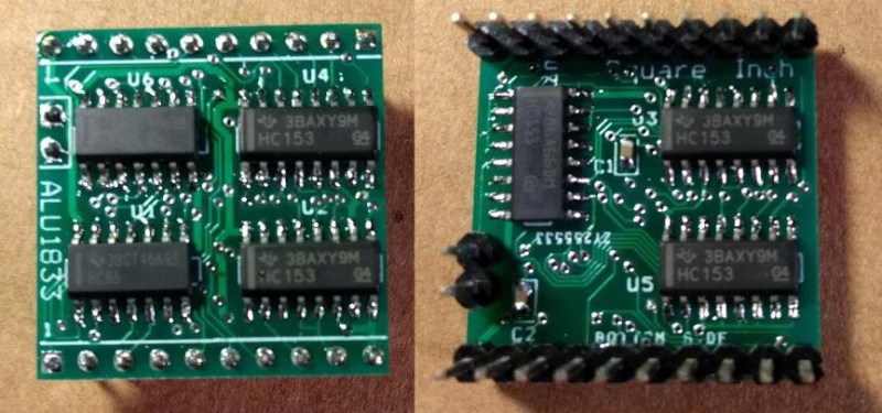
An ALU is built into modern processors, but that wasn’t always how it was done. If you’re looking to build a recreation of an early computer you may need a standalone, and that’s why [roelh] designed an ALU that fits in a square inch piece of circuit board using five multiplexer chips and two XOR chips.
One of the commonly used components for this purpose, the 74LS181 ALU, is not in production anymore. [roelh’s] ALU is intended to be a small footprint replacement of sorts, and can perform seven functions: ADD, SUB, XOR, XNOR, AND, OR, A, B, and NOT A. The small footprint for the design is a constraint of our recent contest: Return of the Square Inch Project. Of course, this meant extra design challenges, such as needing to move the carry in and carry out lines to a separate header because there wasn’t enough space on one edge.
Exploring the theory behind an ALU isn’t just for people building retrocomputers. It is integral to gaining an intuitive understanding of how all computers work. Everyone should consider looking under the hood by walking through the nand2tetris course which uses simulation to build from a NAND gate all the way up to a functioning computer based on The Elements of Computing Science textbook.
If you’re a homebrew computer builder, it might be worthwhile to use one of these ALUs rather than designing your own. Of course, if building components from scratch is your thing we definitely understand that motivation as well.


When I was in college back in the mid 70’s, I worked at popular (back then) electronics place called Burstein-Applebee, or more typically, just BA. We stocked Motorola “replacement” semiconductors and they came out with an experimenter’s series. One of those parts was a half-adder (see http://isweb.redwoods.edu/instruct/calderwoodd/diglogic/half-add.htm) that as the name implies, requires two of these to create a “full” 1 bit adder with carry logic. RTL was the first generation that replaced the discreet logic “boards” used in most computers up to the late sixties and early 70’s. I think I still have a couple of surplus boards from McGee Radio (and other local KCMO electronics store popular in the 70’s).
AMD Am2900 series.
I’m amazed that that’ AMD bipolar 4 bit slice was released back in 1975. That’s when they started and kept going for another 10-15 years. All the big semis did them: Intel, Fairchild, National, etc. Motorola specialized in high speed ECL.
I should of looked up the origin of RTL in Wikipedia earlier. It says the first RTL IC was made in 1961 and used in the Apollo missions starting in 1966. I forgot to mention that the Motorola experimenter’s product line was the “HEP” which one blog says is: “Hobbyist, Experimenter, Professional”. Reasonable.
I still have a textronix 4054 graphic workstation (green screen) with the tape drive and storage screen running basic with that set of those AMD alu and support chips as core processor. Heavy beast, had 4 others around 15 years ago scrapped for parts lot of heatsinks on the back for multiple power supplies.
Wow, a half-adder is just a XOR and an AND. Together on just one chip! Nowadays you could do it smaller with discrete surface-mount components.
I wonder about RTL, since in modern CMOS the “resistors” are actually just the same FETs the logic is made of. Was that not the case in RTL? What did they use for the resistors and transistors (presumably bipolar?) on one type of substrate?
And shouldn’t “substrate” actually be “stratum”, while I’m being pedantic?
RTL used bipolar transistors. And I’m pretty sure most resistors in ICs then and now are just that – resistors (see http://www-inst.eecs.berkeley.edu/~ee40/fa03/lecture/lecture19.pdf). In 1975, I took a semiconductor design course (dropped course after a few of weeks for “home issues”) where the instructor said the final was to design a 4 bit ALU similar to the old TTL 74181. Back then, IC resistors were definitely just resistors (based on sheet resistance of how much you dope a section of Si substrate). High-resistance resistors use polysilicon. TI used to sell Sensitors (see: https://en.wikipedia.org/wiki/Sensistor) that were Si based resistors in axial form (looked like fat epoxy diodes) which had a positive temp co like Si itself. I think the only resistors that are FETs are those in some micros for I/O with a programmable pull-up and/or pull-down. All of that came after someone conceived the idea of Tri-state for bipolar logic (National trademarked Tri-state and sued if you used that without a license).
I wonder where we would be if the ALU was never invented, if computers computed using analogue circuits. It would be a totally different world.
analog circuit for multiplication https://en.wikipedia.org/wiki/Analog_multiplier
analog circuit for division https://www.edn.com/design/analog/4317160/Analog-divider-uses-few-components
analog circuit for Summer https://www.electronics-tutorials.ws/opamp/opamp_4.html
analog circuit for Subtractor https://www.electronics-tutorials.ws/opamp/opamp_5.html
Very likely a world without the Internet.
Fallout, must have had an internet?
An analogue Internet! Likely balancing the long-distance cables would have been a pain in the arse. And to make up for long-distance signal problems, it’d probably be high voltage. Lastly, you’d read your Hackaday posts on the needle of a panel meter. The scale would be marked in both volts and the alphabet.
It is possible to build a computer without ALU. I’ve done that in my project One Square Inch TTL CPU https://hackaday.io/project/161251-1-square-inch-ttl-cpu !
AFAICT, this was first demonstrated by Raul Rojas in 2010:
http://www.inf.fu-berlin.de/inst/ag-ki/rojas_home/documents/tutorials/SmallestCPU.pdf
I dunno about “first”, the IBM CADET in the 1950s didn’t have an adder on board. I think it used look-up tables for adding. CADET wasn’t it’s official name, but an appropriate one.
When I said “demonstrated”, I meant “proven” theoretically.
Bloody heck, that’s interesting! And your Neuron Zoo looks fascinating too, off to check it out, though the more exotic areas of “Turing complete” are where my faculties start to fray a bit. Or OTOH where I need to start doing actual work. Possibly with a bit of paper.
Have you considered Dieter’s concept at http://www.6502.org/users/dieter/a1/a1_4.htm for the LU, and http://www.6502.org/users/dieter/a1/a1_6.htm for the ALU? If you remove the right-shift stage, you get a 2-stage design that uses 4 multiplexers chips and 1 adder for all of the ‘181 functions and more. You can use a decoder and a diode matrix to reduce the number of control signals, giving a 5+1 chip design for 4-bits, or 10+1 chip for 8-bits (as used in the Gigatron).
Hi Marcel, one of the objectives for the project was to show that you can have ADD and SUB functions without using an adder chip, so with logic chips only. Also, I didn’t want to copy your Gigatron design.
Plus, going that small, you cannot find adders.
I suspect you can get rid of one or two chips by replacing the 2x ’86 chips and ‘151 with a single ‘283 adder. It has a fast carry. And optionally adding a decoder to reduce the number control signal (it wil have 4+4+1 otherwise).
I know you will never read this (RIP). True, but there are no adders that small in the 3.3v or lower range. When you want to go really fast, you have to be creative, and more of the smaller chips is often faster.
And for the Gigatron, a redesign that uses 3 adder chips and another mux (or two if you need the carry) can get the latency down further. And really, to go beyond the 15 MHz you got on your experimental build, I’d add another adder and mux, and also replace the control unit and ROM with 2 ROMs and enough registers after them to keep the delay slot. So have decoded line data as the ROM, There are 19 control signals and 8 operand bits, so 27 bits. That can be compatible with the original since you can write a quick program to read the ROM image and convert to the expanded ROM format. And if you write an assembler to work with the new format, you could also use opcodes that don’t exist already by using control line combinations the decoder cannot do. Plus, with 5 leftover bits, one could add new instructions with those.
Thank you so much for giving us the Gigatron TTL Computer.