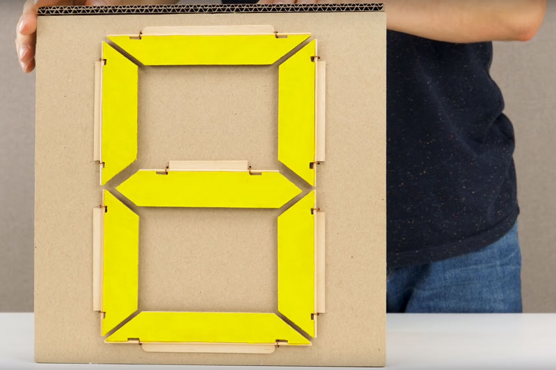
We’ve seen a variety of oddball 7-segment displays in the past, but this one uses a new material: both for the display and the mechanical mechanism that drives it; cardboard. Yup, the whole thing is made from cardboard, wood and a few rubber bands. [The Q] shows how he put together in this nice video, starting from first principles that show how the segments are made: simple pieces of cardboard painted on one side with fluorescent paint. A piece of wood pushes the element out to blank it, and each element is connected to a cam wheel that pushes the wood in or out.
The really clever bit is that [The Q] mapped digits 0 – 9 onto a matrix for which of the 7 segments is “on” or “off”. He then used this information to create a stack of 7 cams on a central axle. As you rotate the axle, the cams turn, moving the wooding arms. The arms then cause the elements to flip as they count up through the digits. In essence, he engineered a physical decimal to 7 segment decoder, much like the electronic one inside the SN74LS47. The whole assembly is capped by a knob that indicates which digit is currently displayed. If mechanical displays like this are your thing, check out this one made from LEGO parts, or this awesome 3D printed creation.


I love the build and the video. I hope it inspires more people to build passive designs out of cardboard. It’s an underappreciated building material.
Oddball? I think it is great!
Not sure why the cams are made to turn only one direction. Why not make them ramped in both directions?
Probably for really crisp / snappy changing of the segments?
Now he has to build a clock.
Cardboard clock with cardboard escapement and spring/weights?
I think it is an ingenious build, but it is built out of really bad materials. It will not last long indoors and outdoors forget it. Also the digits should be behind something so you can not see the unflipped side, or the design should be modified so it fully turns the segment over so the bright side can not be seen at an off angle. I love the engineering that went into it though on a more practical scale, I like my hand operated solution better, https://hackaday.io/project/161215-largemechanical-hand-activated-7-segment-display Much less to go wrong and much more weatehrproof. So far it is standing up well to weekly use outdoors.
Great material for a proof of concept or prototype though.
I usually start with cardboard before I move to wood because when I am done I can use the cardboard as a template.
Cute :-) Now please make a hexadecimal version ;-)
^^ this +1
This is pretty durn cool, and there are some other pretty-durn-cool vids on that channel.
Couple thoughts:
1st: aaarrrgggghhhh! it bugs me to no end how much effort was clearly put into this, surely several builds from the first proto to the filming, and clearly some decent amount of post-vid-processing, etc. yet the dang thing doesn’t flip the flaps far enough to hide the paint! which got me thinking:
2nd: Why? What was the motive of “The Q”? Who’s the target-audience? Who IS The Q? Etc. Which got me viewing their other vids, looking at subscriber-numbers, etc. Which arrived me at the conclusion:
3rd: “The Q” is NOT A “HE”, but a COLLECTIVE. A group of folk.
4th: Even if “The Q” paid the designer/builder for every vid they are a part of, surely the hourly-wage would be miniscule. Consider the Mario-Rat-Maze in which we’ll call the builder “Q” [as opposed to “The Q,” the collective]; Q uses a tiny paintbrush to cover a gigantic area. Hours in unnecessary-albeit-well-done details. Craftsmanship, surely, but, like the fact surely at least two of each build must’ve been done, in addition to design, and plausibly a couple revisions, a *lot* of effort goes into each of these vids, not only on the part of the designer/builder, but also the videographer, etc. So, what’s it boil down to?
5th: Q may be a bit of a basement-builder-craftsman who, although clearly deserving of 5million followers, probably couldn’t manage the overhead; filmography, post-processing, nevermind the celebrity, nevermind the shear number of and rate of vids necessary to gain such a following. And with so much effort in design and building of each project, Q couldn’t possibly be responsible for all the builds in all “The Q’s” vids. Thus:
6th: there must be several Q’s in The Q. (assuming Q’s are builder/designers, but then, what are the filmographers called?)
The thought-process continues, but I’ll spare you the details…
Very Cool, but I think Q was focussed mostly on the cam-system, as opposed to the display, and unfortunately the filmographer gave almost as much screen-time to the painting as the cams. Meanwhile, only a slight design-revision (version 1.2) would’ve removed the arrrrgggghhh-factor… which, plausibly, Q left-in due to the realization, from previous-endeavors with The Q, wouldn’t be covered by the budget. AAAARRRRGGGGHHHH
ha, I enjoyed reading this. It’s quite interesting, so many subscribers for such a new account, and some of the videos have +200mil views..
To add to the conspiracy: QAnon
That’s a pretty nifty Labo kit! :P
Should paint black
With THAT brush? Would take all week. Teach a man to use a Sharpie, and … I thought I had something there.
Cool idea. This has given me the idea to do an electronic version, by using 7 servos to turn the segments MSP430 and Forth is the first version, then Arduino and RPI. I will give it a try to use the 2313, based on https://www.amazon.co.uk/ATTINY-Forth-Project-Combined-English/dp/172662692X/ref=asap_bc?ie=UTF8 and the segments mounted directly onto the RC Servos – they can turn about 180 degrees. And the first clock would just use one of those and display hours and minutes sequentially.
Brilliant, someone’s been thinking and with directed focus for presentation too, good video and thought provoking as well, thanks for the thread, cheers :-)
If I stuck a rubber band to cardboard with glue, you can be assured that it would ping off the first time I pulled on it.
Unbelievably cool.
This is so far beyond anything I’ve ever attempted to do with cardboard. Color me impressed!
I’m ambivalent about this .. points for a cool build, and for using inexpensive materials that pretty much anyone can lay hands on. But there seems to be undue complexity in the design .. lots of individual parts, and a lot of labor putting them together.
If you’re going to make an examplar for upcycling, it should probably embrace design elegance as part of the effort. This build is definitely inelegant .. in fact, it almost seems to go out of its way to be complex. And it’s almost certainly not durable (all of the components are a bit janky, and there are lots of them) .. so it pretty much serves an example of how to get inadequate return per unit of effort.
Now, make it random access. ;)
Cool build! Now make it alphanumeric. :grin:
You want that in dot matrix (flip dots) or 15-segment?