There is a certain sense of accomplishment one gets when building their own tools. This is what [Alejandro Velazquez] was going for when he built his own soldering station. Sure you can get a decent station for a pittance on Amazon, or eBay. You can even build your own microprocessor controlled station. [Alejandro] is currently interested in analog electronics, so he went that route to build his own closed-loop station.
The handle is a 50 watt, 24-volt affair with a thermocouple. You can find this handle on many Hakko 907 clone soldering stations, often referred to as the 907A. The station itself is completely analog. A triac switches the current going to the heater. The triac is controlled by a PWM signal. The PWM itself is generated and regulated by an LM324 quad op-amp, which is the heart of the station. The op-amp compares the setpoint with the current temperature read from the soldering handle’s thermocouple, then adjusts the duty cycle of the PWM signal to raise, or lower the temperature.
It’s a classic control system, and the schematic is definitely worth checking out if you want to understand how op-amps can be used to create complex operations.
You can find plenty more information on analog electronics right here on Hackaday — we’ve covered thermocouple amplifiers, as well as instrumentation amps. If you’re more of a digital man, check out this Arduino controlled soldering station!


Great learning-experience!
I once designed a light-dimmer using solid-state relays, precisely timing each activation with the mains zero-crossing, and deactivation somewhere inbetween for the duty-cycle (or was it the opposite?) giving a 60Hz pwm-ish frequency. As I understand, this is how incandescent light-dimmers usually work. (and, thus, maybe the “ringing” sound produced by the filament?)
I figured he mighta done similar and was curious how that’d be done in analog.
More-interestingly, I found he chose a lower pwm-freq than 60Hz, such that switching *only* occurs at zero-crossings. Both on and off. Thus no current-surges.
Also, his PWM-setup, then, linearly controls the power with a linear change in duty-cycle (albeit in steps), whereas the ‘dimming’ circuit’s power output varies sinusoidally (?) with a linear change in duty-cycle.
Clever technique; going in the ol’ toolbag.
Common dimmers fires at variable delay from zero crossing as their TRIAC once fired will remain conducting until (very shortly) at the next crossing.
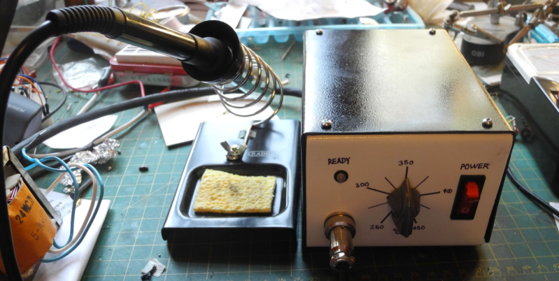
Can anyone tell me where I can download the font he used for the front panel decal?
I noticed the units on the dial are degrees Celsius and it goes from 260 to 450. That makes me wonder where the tubes are for the oxy and acetylene lol
Jokes aside, the good ol’ linear PSU will probably last forever.
The circuit diagram is near perfect. It distinctly flows from left to right.
A metal oxide varistor or an active transorb would be better than the zener in the PSU. Zener diodes have two failure modes: 1) Short circuit 2) Completely missing. There are a little like TRIACs. I have never seen a faulty TRIAC but I have often seen the three legs left behind.
It takes an immense amount of energy to change an electromagnetic field rapidly so voltage spikes don’t get through transformers until just after it explodes. You only need to deal with surges after a transformer.
A MOV can silently fail eventually as it wears out clamping surges.
HAD writers need to write an article about surge suppression – something that many EEs do not correctly implement; and no, I will not do freebie writing for your corporate moguls. Here are some clues to get you started.
IEC61051-2 (UL1449 should be considered deprecated)
IEC61000-4-5
IEC6950-1, clause 1.5.9 and annex Q
Understand the OV category for your equipment.
BTW there is a 220R (R16) on the return path of the Zener as it is used as a shunt regulator not a surge protector. Resistor will limit current to within parts’s spec (if designed correctly). Only failure mode might be a cold solder joint opening up the connection to the diode.
The way the schematic drawn with that node marked as ”GND” is bad.
Yep, I missed that – thanks.