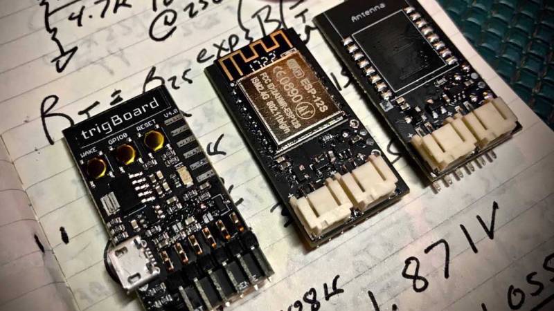
Given the popularity of hacking and repurposing Amazon Dash buttons, there appears to be a real need amongst tinkerers for a simple “do something interesting on the internet when a button is pressed” device. If you have this need but don’t feel like fighting to bend a Dash device to your will, take a look at [Kevin Darrah]’s trigBoard instead.
The trigBoard is a battery-powered, ESP8266-based board that includes some clever circuitry to help it barely sip power (less than one microamp!) while waiting to be triggered by a digital input. This input could be a magnetic reed switch, push button, or similar, and you can configure the board for either normally open or normally closed switches.
The clever hardware bits that allow for such low power consumption are explained in [Kevin]’s YouTube video, which we’ve also embedded after the break. To summarize: the EPS8266 spends most of it’s time completely unpowered. A Texas Instruments TPL5111 power timer chip burns 35 nanoamps and wakes the ESP8266 up every hour to check on the battery. This chip also has a manual wake pin, and it’s this pin – along with more power-saving circuitry – that’s used to trigger actions based on the external input.
Apparently the microcontroller can somehow distinguish between being woken up for a battery check versus a button press, so you needn’t worry about accidentally sending yourself an alert every hour. The default firmware is set up to use Pushbullet to send notifications, but of course you could do anything an EPS8266 is capable of. The code is available on the project’s wiki page.
The board also includes a standard micro-JST connector for a LiPo battery, and can charge said battery through a micro-USB port. The trigBoard’s full schematic is on the wiki, and pre-built devices are available on Tindie.
[Kevin]’s hardware walkthrough video is embedded after the break.
[via Dangerous Prototypes]


1uA? That’s less current than flared jeans.
This is a worthy first post!
I used it in one of my projects and also measured the total consumption. It was 65 nA when the ESP was off. Cool product ( https://youtu.be/a2MiyFGWnU0 )
It’s a great little board, Kevin put a lot of work into it and it shows.
Nice.
I, personally would’ve used an ATTINY for the wakeup circuit, but only because I’ve done this before, and therefore know how to do it, and I already have lots of them, and they are easy to get.
Also:
TPL5111 : $0.77, ATTINY9: $0.30 (single piece prices from Mouser)
The power consumption with running watchdog timer is higher, though, about 5µA.
But having a micro instead of a hardware times makes it also possible to use more flexible wake options, like multiple wake sources with filtering, flexible sleep time, depending on situation and battery level, etc.
When it comes to mass production, you have of course to calculate also the programming costs.
If you’re happy with 2 orders of magnitude higher power then you’re probably also okay just dumping the ESP8266 into deep sleep since that also uses microAmps of current.
Does it really have to be 65nA, when the ESP8266 wakes up for a few seconds every hour?
Let’s assume it needs 5 seconds to boot, connect to WiFi, and send some data. It’ll need about 200mA during that time. That’ll make an average current of ~278µA.
In this case, the 5µA of the wakeup circuit don’t really matter.
If you wake up only once a day, or only on demand, then it’s a different thing.
I totally agree with your comment. I’m seeing more like 10-12 seconds on my Wifi with WPA2.
Disable dhcp, use optimised firmware and get milliseconds
https://esp8266.ru/forum/threads/ehnergopotreblenie-esp-itogi.3001/
Or use ESP-now mode instead of standard wifi; max 20 nodes (uses MAC Addresses), 256 bytes per packet, no router or AP so no (direct) internet connection
Any link to this circuit or hardware? I like to make some for myself.
A nitpick: I’ve characterized the TPL51xx timers, using them to drain a 10uF film capacitor, buffering the cap voltage with a femtoamp op amp, and tracking the amp’s output voltage.
The timers do hit the 35nA banner spec, but only when the supply voltage is below 2.5V. At the 4.2V mentioned in the video, they draw about 100nA. That’s excellent performance (a little less than 1mAh per year), and well below the 1uA quoted for this project, but not quite as amazing as the first page of the datasheet would have you believe.
More nitpicking: looking at the TPS3839, it has a supply current of 150nA typical. And the TPS73733 has a typ current of 20nA when disabled. So looking at several hundred nanoamps.
I’ve been playing with something similar and this would be useful to me.
The main difference is I’ve used variable resistors to set the timer for different periods.
I’d buy one to try out but as it’s got to come from the states to me in the UK the postage doubles the cost of the board.
I may not be into these type of devices, but if this is about a device that only waits for a button press, then why not make device that is totally powerless and that does the requested action upon boot-up?
The button can then be to connect the battery to the device ;-)
Nope, as per the article, theres also a timer to wake it up periodically.
Thats what the TPL5111 is for.
That requires power.
It has the added benefit of waking periodically, therefore you can check battery status and make sure it is still working. Otherwise yes, you could use a capacitor and latching circuit to keep the ESP alive. Without the latching circuit, you would have to hold the button down until the wifi has done its thing.
You can, except you’ll need enough time to boot, find a WiFI network, ask to join it, do the crypto challenge-response to authenticate, do the DHCP 4-way to get an IP address, possibly do a DNS lookup, probably do a 3-way TCP handshake, etc etc etc, and someone is unlikely to hold the button that long… so you need something that will “latch it on” until you’re done and you’re told to turn off again. Of course you can design a circuit to do this for you – doing so with a miniscule quiescent current is not impossible but harder than you might expect if you want to avoid various noisy false triggers.
If you also want to add a timer to wake up and self-test / phone home periodically, you’re obviously also going to want to tell your ESP (or whatever you woke) whether it’s being awoken for a button-press or a timer-fire. Pretty soon you’re gong to end up with something much larger, and drawing more quiescent current, than the TPL5111.
Sometimes it’s easier to just add a small chip – someone else has put all the thought, design, miniaturisation, and construction time in for you :-)
You can do it with zero off-current if you only want a button. You power your micro through a relay (higher power use) or a transistor, which is switched on by the micro as one of it’s first actions. You get power in the first place through the button, bypassing your relay / transistor. It’s something I did for a kid’s toy I made, since young kids aren’t going to remember to switch things off.
It wasn’t a super-low-power thing but was going to be off most of it’s life, so the higher on-current was a good tradeoff.
That’s why you latch on poweron. The ESP8266 takes only a couple of milliseconds to start. The first action should be to latch around the power button. Do it’s stuff and then commit suicide by releasing the latch :)
Hi,
Same kind of architecture here. http://faire-ca-soi-meme.fr/domotique/2017/01/20/capteur-temperature-humidite-wifi-sur-pile-a-moins-de-10-euros-hardware/
Really great component
Does getting below 1uA actually make a material difference in battery life? I’m pretty sure those Lithium Ion packs have a self-dishcarge rate > 1uA.
I also think more people should look at LiFePO4. Fully-charged they output 3.3V and have a very flat discharge curve, so they can be used without a regulator, and therefore avoid quiescent regulator losses.
It’s hard to say until you amortize the current consumption.
The project above turns on once per hour. Let’s assume it stays on for 100ms and (knowing the ESP8266) uses about 100mA during that time. That amortizes out to about 2.8uAh of stored charge.
Adding 1uA of self-leakage and 1uA of idle current takes the total amortized current consumption to about 4.8uA per hour. In that budget, the two terms that represent pure loss come to 40%, and idle current is half of that.
Taking the idle current down to 200nA drops the total budget to 4uA. The loss terms are about 30% of the total. The idle current is about 5% of the total and about 17% of the waste.
That’s an improvement worth considering.
Dropping the idle current to 50nA would drop the total budget to 3.85uA, with idle current being about 1.3% of the total and about 5% of the waste. At that point, you’ve probably hit the point of diminishing returns when it comes to reducing the idle current.
Staying on for 100ms is a pipe dream if you want to connect to wifi and say hello to some server… More like 10 seconds…
You can shave off some time by hardcoding the IP and not using DHCP.
I’m more than a little surprised that the TPS3839 works as desired in this circuit, as the chip is not guaranteed to pull the output low when the input voltage is suddenly removed like this. It needs at least 0.6V to operate. It seems there must be enough parasitic capacitance on Vdd to keep it alive long enough for it to pull its output low. You see, it needs energy from someplace to charge the gate on the output pull-down FET. I would recommend adding a -tiny- bit of capacitance between pins 1 and 3 (but only like 0.001uF – so as not to slow down the response time; this capacitance equates to roughly 6ms of delay) to help assure intended operation. Per the datasheet:
“8.4.3 Below Power-On Reset (VDD < V(POR))
When the voltage on VDD is lower than the power-on reset voltage (V (POR) ), the RESET output is undefined. Do not rely on the RESET output for proper device function under this condition."
Nice circuit though. Very well thought out!
Connect your trigger to the CH_PD (enable) pin. Find a GPIO that’s high at boot, and connect that to CH_PD as well. Now the trigger turns the microcontroller on, and when it’s finished its work it can turn itself off by setting the GPIO low.
I built something similar last year, but only for button press detection and no timed wake up. It used a complementary pair of Mosfets, one half to isolate the power line to the ESP and one half to latch the power. The ESP latched the power immediately after start up. It used UDP to communicate as that is much faster than TCP thus saving a lot of power. It used a pair of AAA batteries and tests showed that they would last several years for the application in question. Although the ESP8266 is not well suited to battery power, using UDP protocols such as CoAP can keep the average power consumption low enough for intermittent signaling with battery power.
Perfect for long battery life on a webenabled smart landmine
Personally I find that it takes quite a long time for the MCU to find the WiFi network, connect to it, get a DHCP address, then send its network message before going back to sleep. For comparison the actual reading of the sensors is quite fast. These networking tasks can easily take 30 seconds or more, and this is the major driver of the “awake time” required (in a high-power RF-on state), which is the major driver of the system’s battery life.
Using UDP makes a lot of difference to the “on” time needed to send a message. If I recall correctly it changed it from several seconds using TCP/IP to under a second of “on” time required to send a message with UDP. If you are just notifying a hub device on a LAN, UDP works just fine. I used a N channel mosfet in the Ground line of the ESP to turn it off in order to remove the ESPs leakage current when it was off. A press button applied power to the ESP and the mosfet and charged up a capacitor to keep the mosfet and the ESP on long enough for the ESP to turn on a P channel mosfet via a GPIO pin (pulled low) to keep the ESP powered. The GPIO pin was toggled high to turn off the ESP after the message had been sent. I have the schematic if anyone is interested. At the time, the Texas devices cost more than the ESP hence the mosfet solution.
I’m interested in your schematic if you could send it. I find that the boot time from power-on of the 8266 is about 10secs which is surprisingly long.